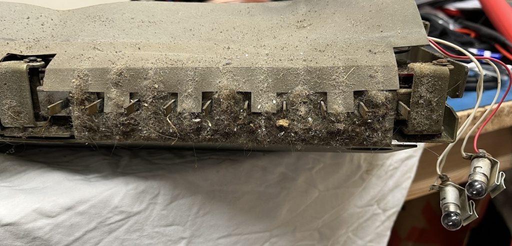
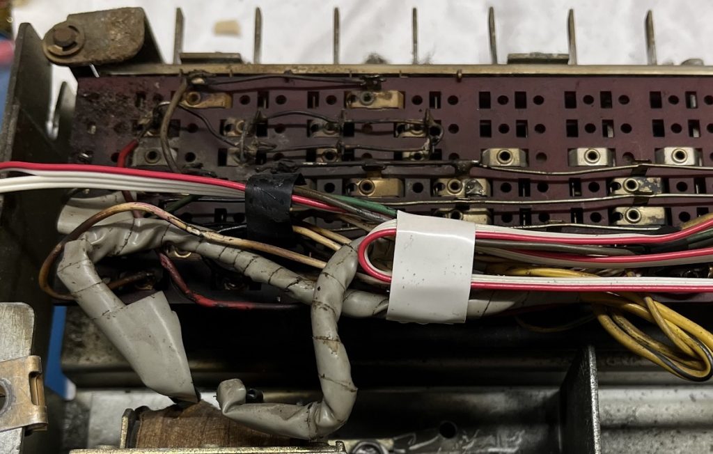
All the push-buttons (30 buttons) in the selector unit needed to be cleaned.
Most of them did not work… 🙂
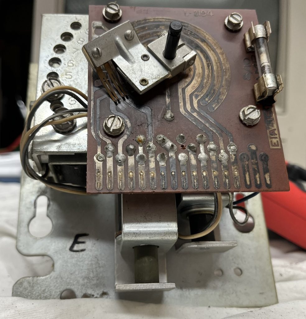
Next up for cleaning is the credit unit.
Rather filthy… 🙂

All the push-buttons (30 buttons) in the selector unit needed to be cleaned.
Most of them did not work… 🙂
Next up for cleaning is the credit unit.
Rather filthy… 🙂
Got the mechanism out on the workbench for a first look.
Some obvious problems, and needs a good clean and lubrication.
This machine is now finished and returned to the owner.
A short summary of some of the repairs :
-CPU-board : Acid damages repaired, and damaged IC:s/resistors/capacitors were replaced.
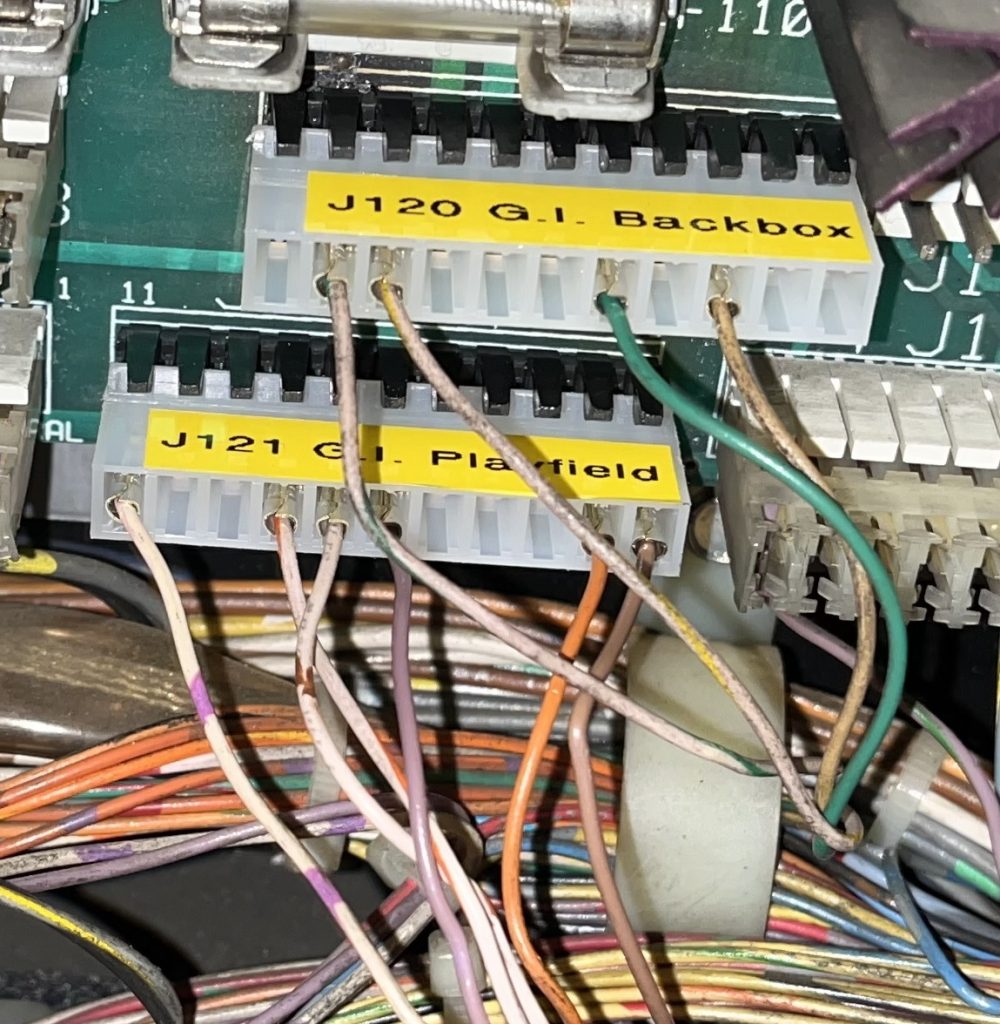
-Driver board : Two new connectors for the G.I. is mounted, and some capacitors were replaced.
-Sound board : Re-seating of all connectors restored the sound.
-Opto board ball trough : Resoldering of all resistors fixed everything wrong with this board. 🙂
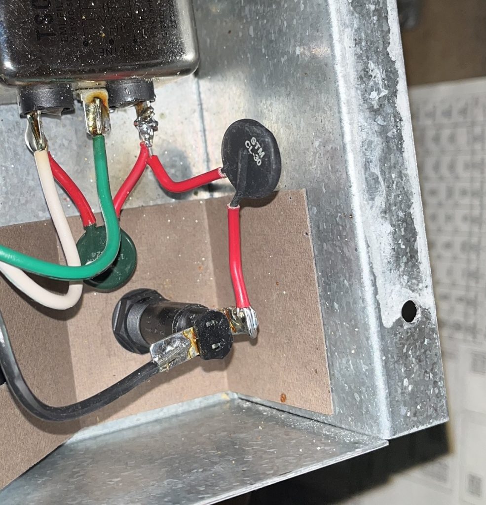
-Thermistor at the line filter was replaced because the old one gave up after about 20 power-ups. 🙂
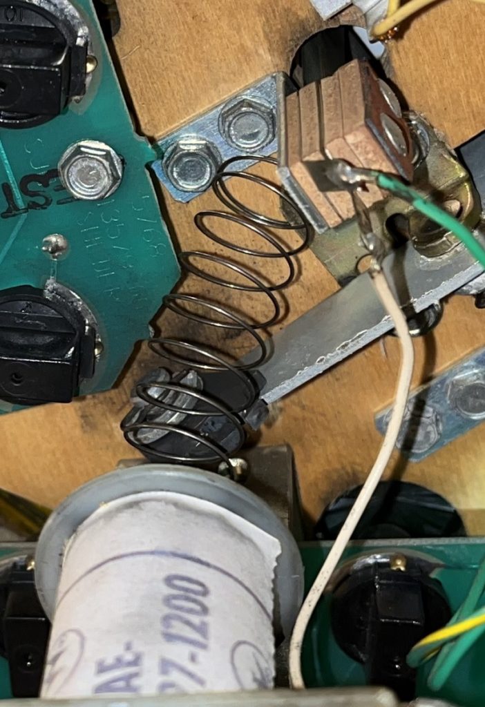
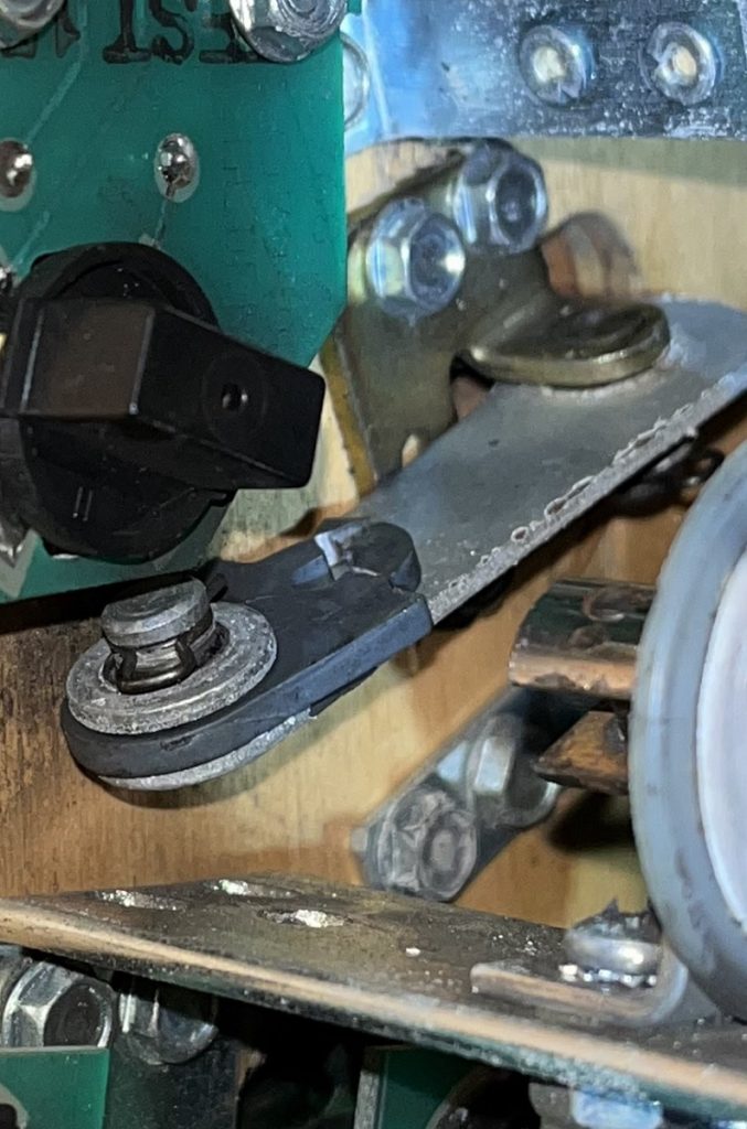
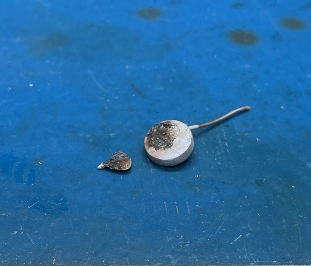
-Linkage to right slingshot were broken off, so it were replaced.
-New bulbs, new rubber and a slight cleaning.
Game now works 100% for what i can tell. 🙂
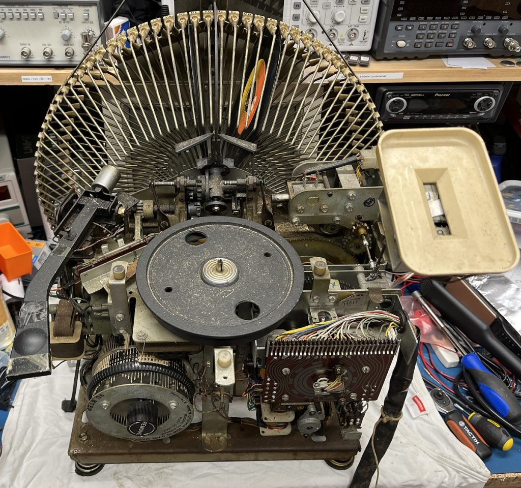
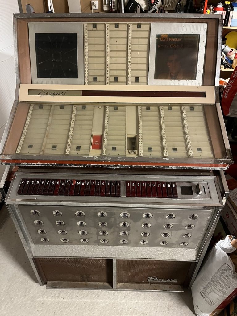
Got this Rowe AMI Tropicana Jukebox in for repair. (JBM-200, 1964)
It is in rough shape and needs a lot of repairs.
I unplugged the amps and powered it on to see what it does.
The lights are mostly ok.
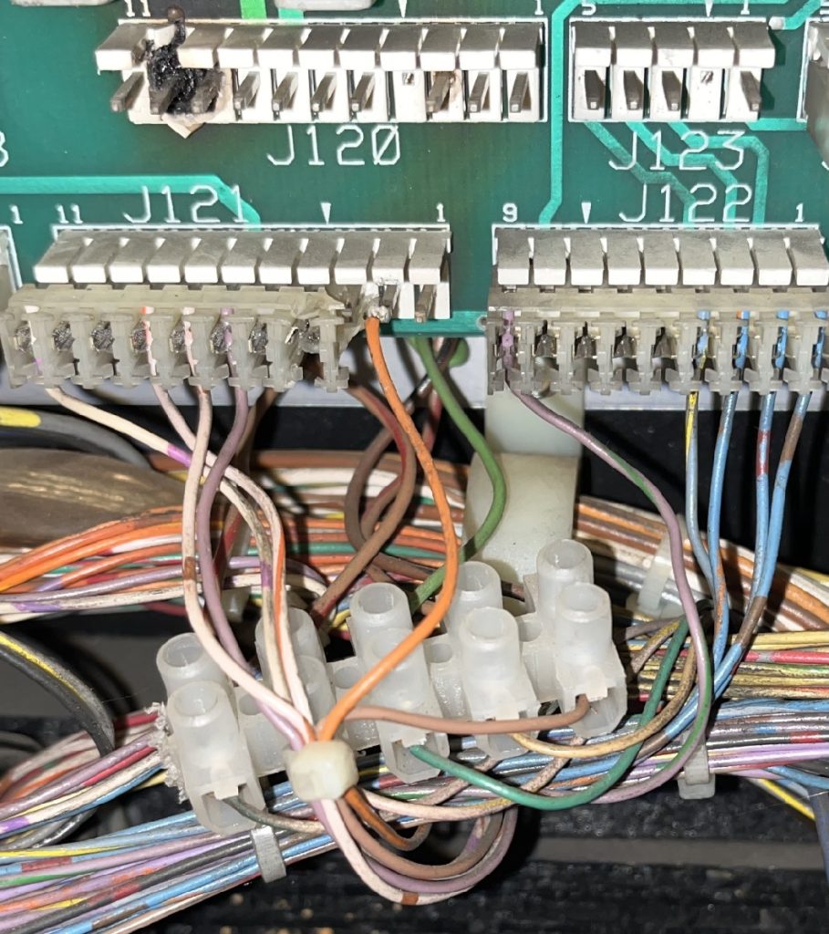
Not responding at all when i tried to select a record using the buttons.
The buttons does not “stick” in pressed down mode either.
And holding down a letter and a number together does not do anything.
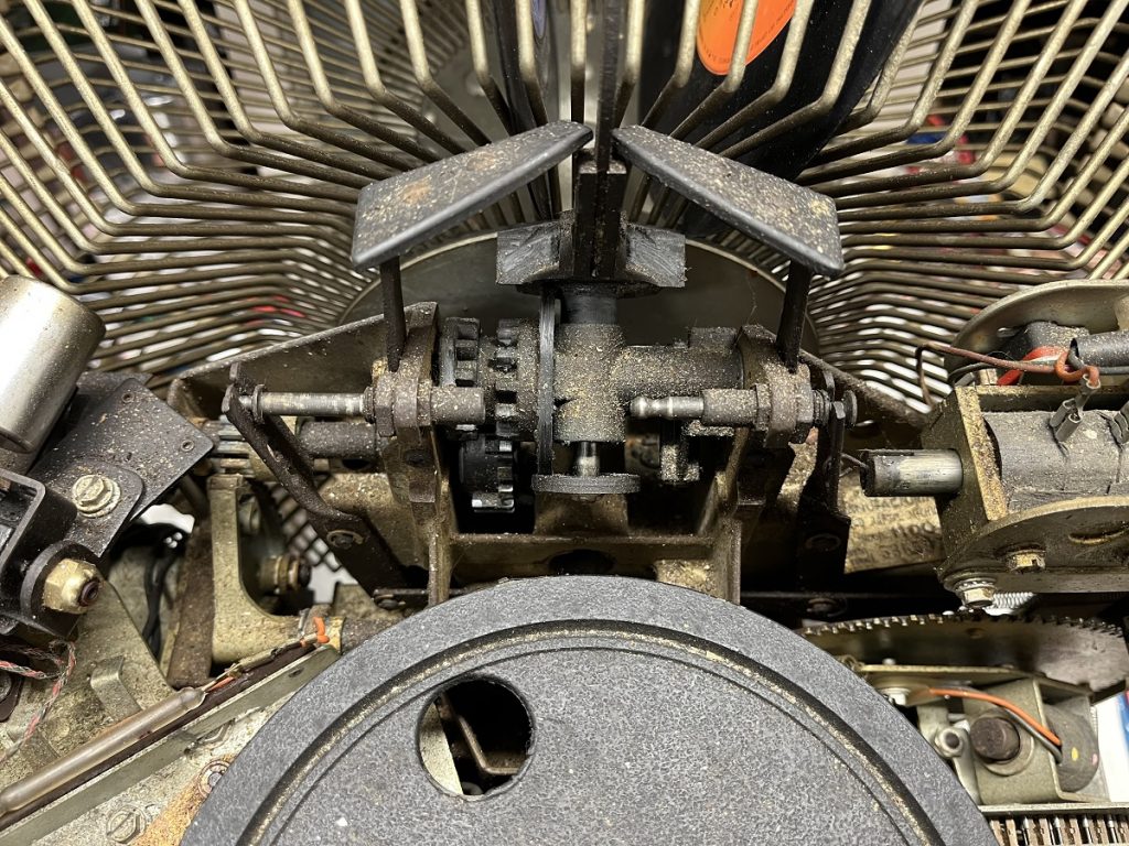
Using the “Scan” button on the inside, it spins the carousel, so that part seems ok. 🙂
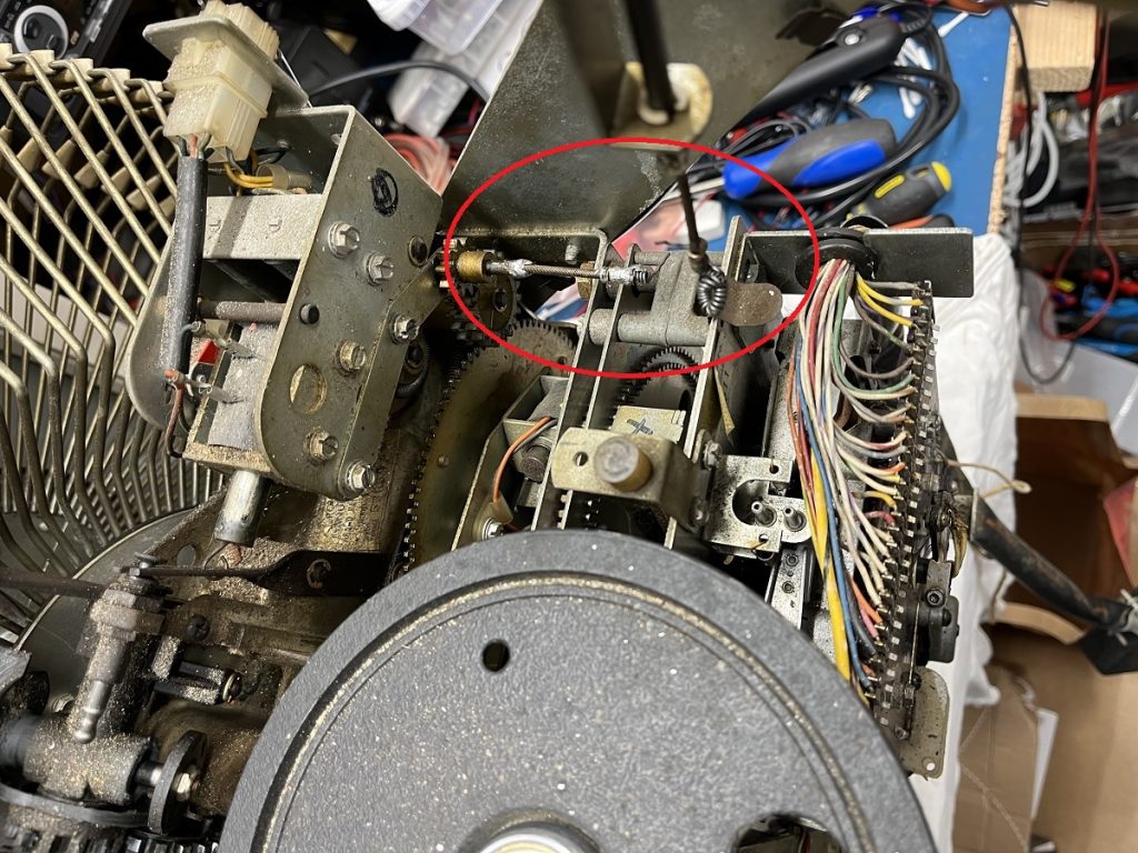
When powered off, manually turning the carousel makes the gripper arm pick up a record and place it on the platter and later put it back, but the tonearm does not move at all.
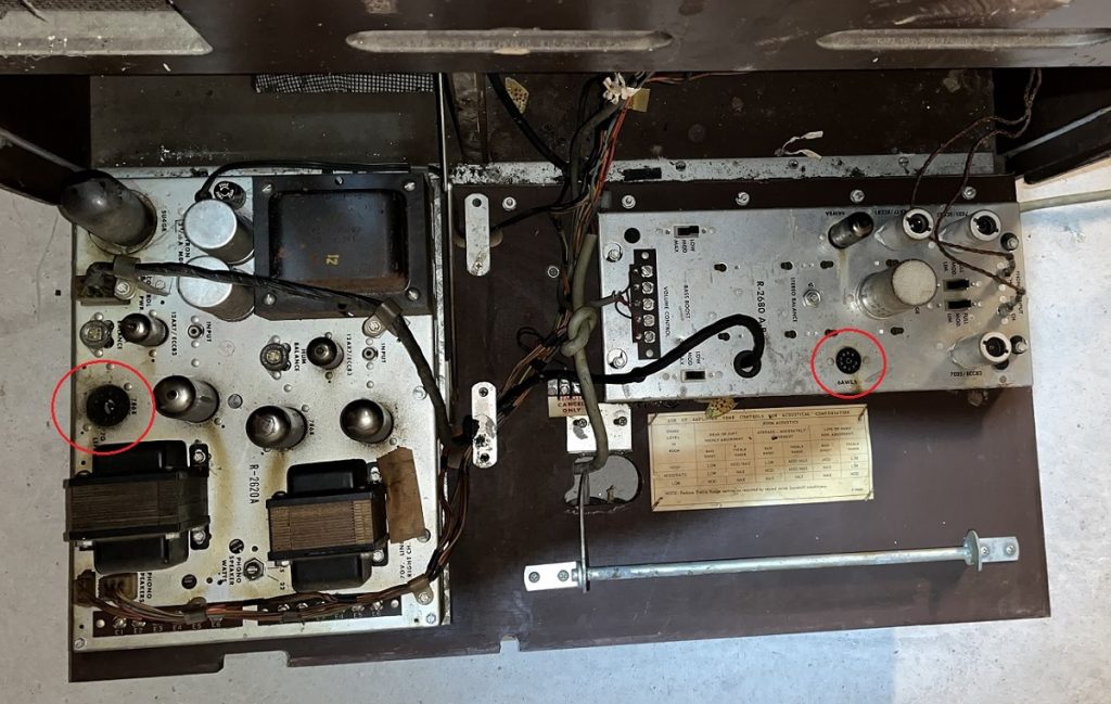
The power amps are missing two of the tubes.
A 6AW8A and, unfortunatly, an 7868…
7868 are hard to get hold of, and really expensive if found.
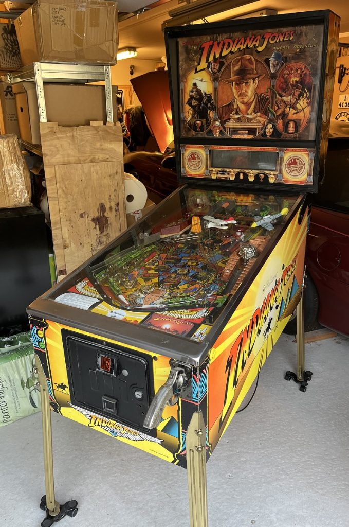
I got this Williams Indiana Jones pinball machine in for repair.
This machine has multiple problems.
It starts up, and it is possible to start a game.
But it ejects two balls every time.
(Bad optos maybe?)
There are no music whatsoever, and no soundeffects, just a random “ding” now and then.
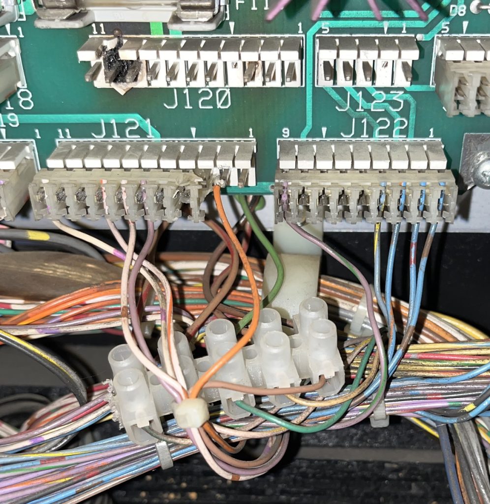
When i tried to get into the test menu, it did not respond to any of the buttons inside the coin door.
So i measured all the cables from the buttons up to the connector on the CPU-board, and they were all ok.
Tested the buttons again, but still no response.
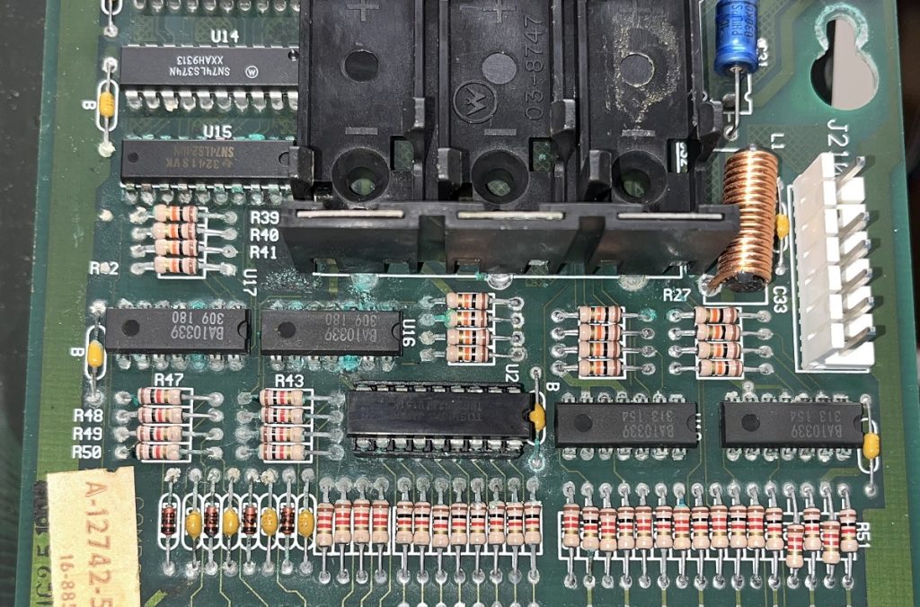
I then removed the CPU-board and placed it on my workbench to give it a good visual inspection.
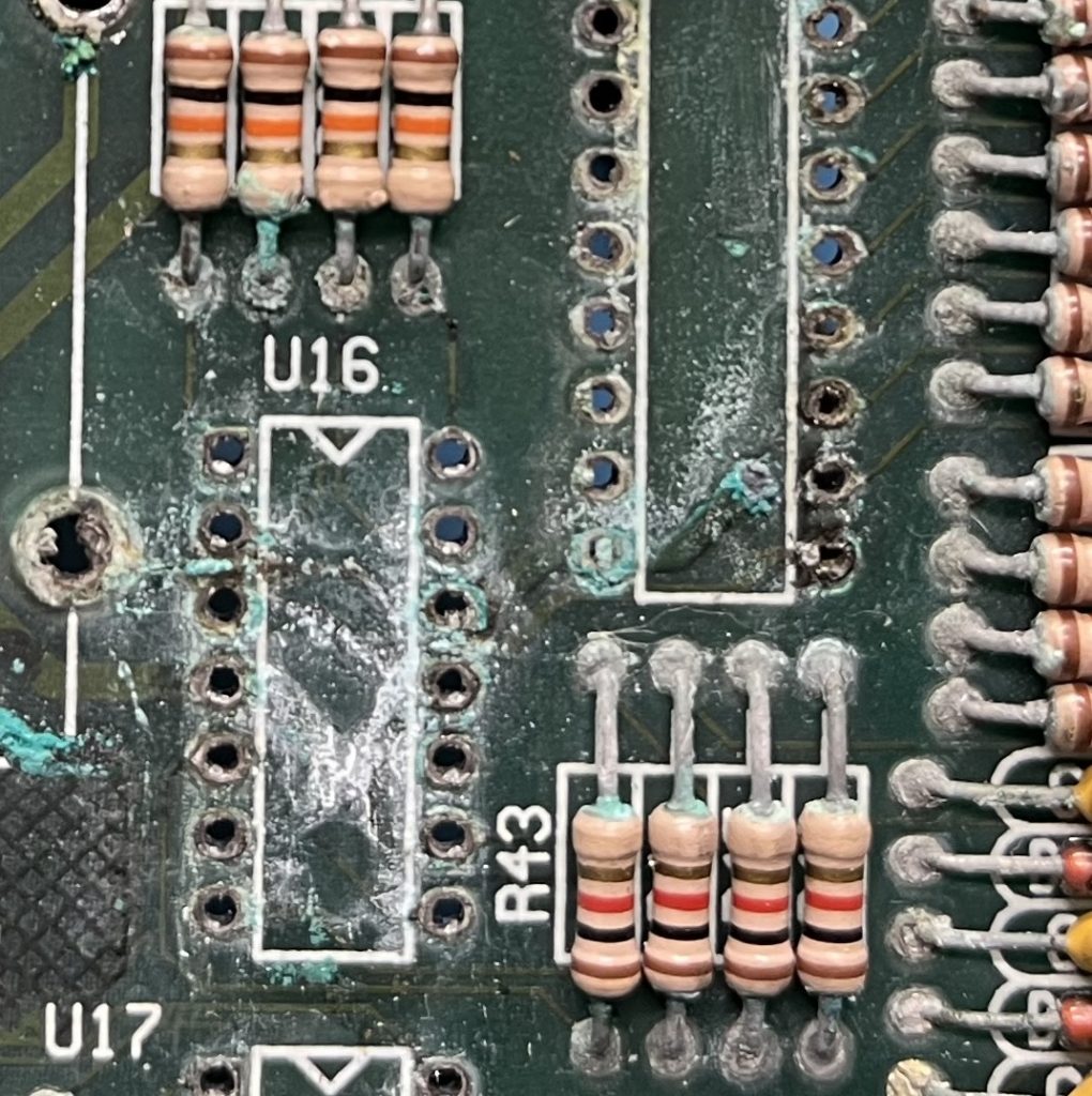
Acid-damage had taken 6 IC:s and some resistors/capacitors…
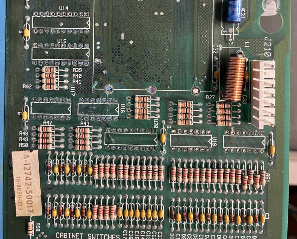
So i removed IC:s and the battery holder, and will clean the board up before putting in sockets and changing some resistors and capacitors.
The driver board also has some damage on some connectors due to heating, and some hacking has been done previously that i have to fix.
Small update :
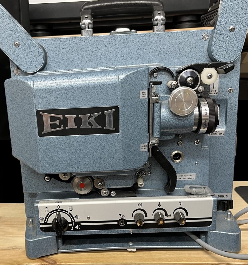
After replacing all of the capacitors on the amplifier board the sound is back to normal, and this Eiki are now fully operational.
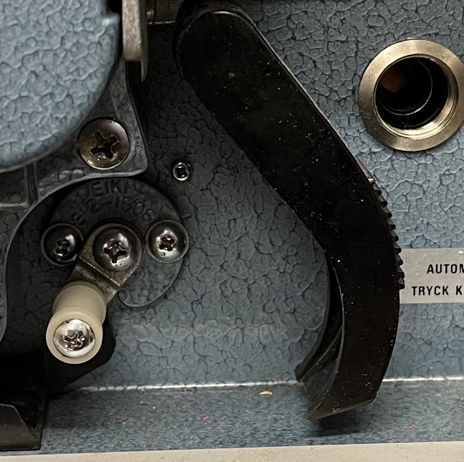
The pressure arm at the sound drum were stuck, and needed a cleaning and lubrication to work again.
And the loop-restorer arm was also stuck, and it too needed a cleaning and lubrication to work.
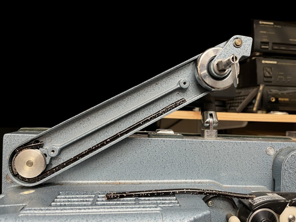
The rubber belts arrived, and are now in place.
And the auto-thread system arm were cleaned and lubricated as well, since it too were stuck.
The projector now works, but the sound is very distorted.
I will take the amplifier board out and see if the capacitors needs replacement.
(They are old, så they may have dried out.)
I did a little modification to the mic input jack, so now it is used as a line out instead.
That way i could connect an external amplifier to check if the sound is distorted before the built in amplifier, or if it is the amplifier itself that is the problem.
Sound were fine when i used the line out jack, so it seems that the capacitors on the amplifier board needs replacement.
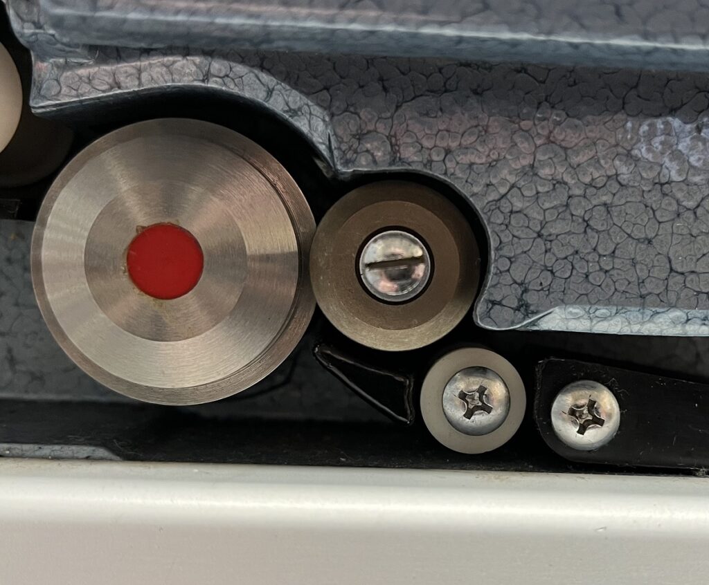
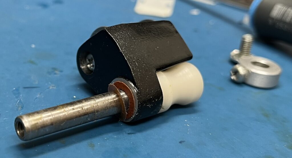
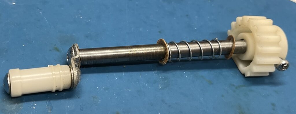
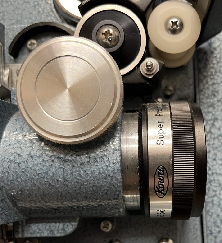
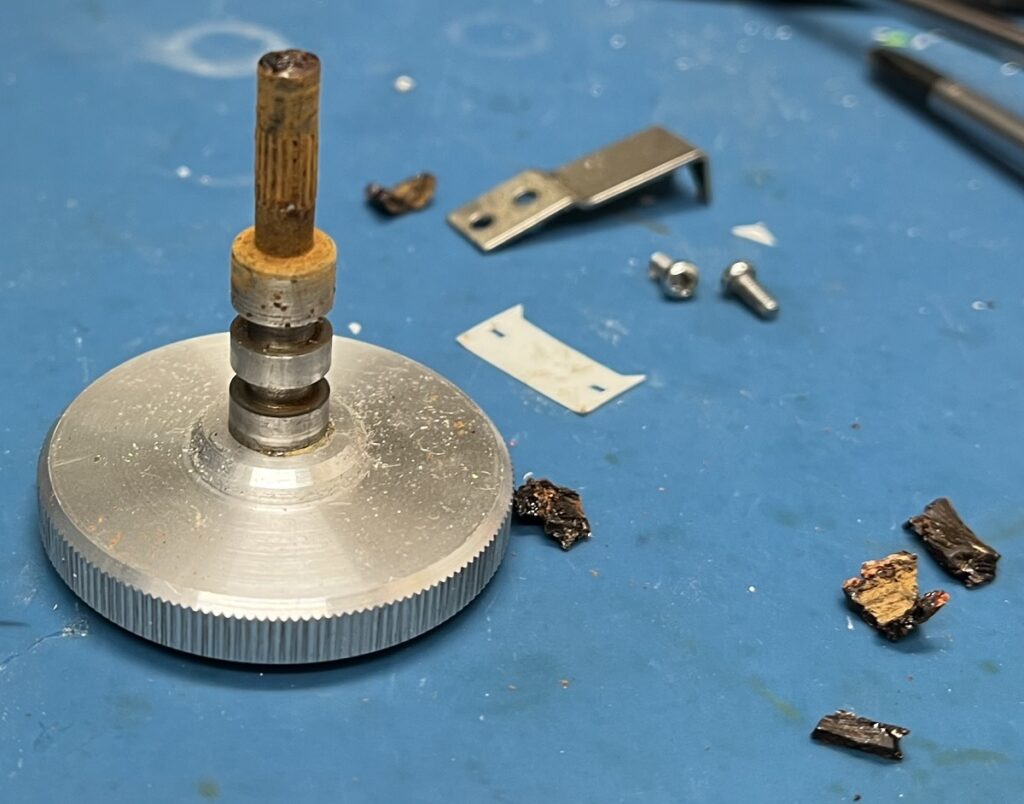
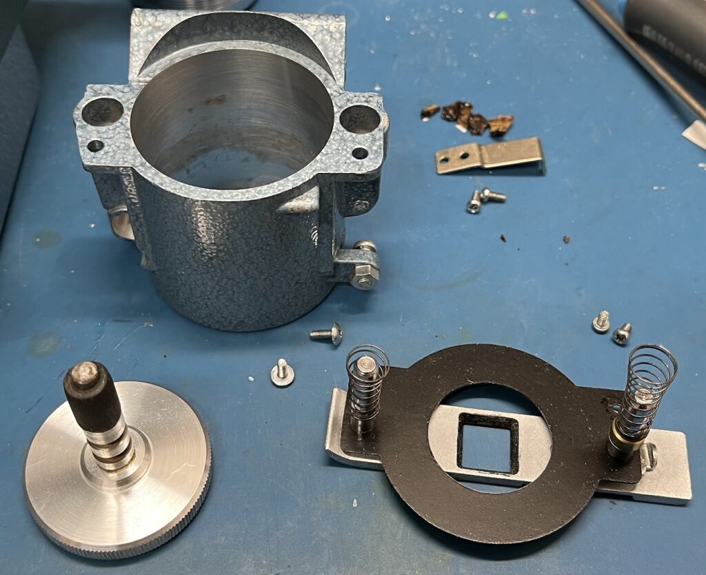
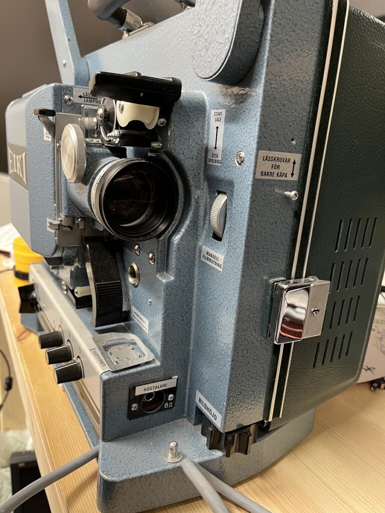
The focus knob did not work, and after disassembly it became clear what the problem was.
The rubber that were supposed to turn the lens forwards and backwards was dried up and had crumbled to pieces.
A piece of rubber hose sandpapered to correct size did the trick.
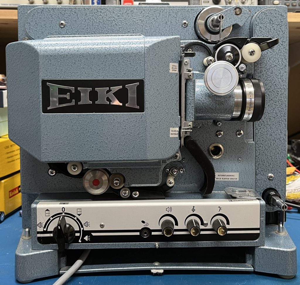
This is an EIKI RT-0 16mm film projector.
It has sat for a very long time and needs an overhaul.
Most of the moving parts are almost stuck, and needs to be cleaned and lubricated.
All of the rubber bands needs to be replaced, since they all have deteriorated.
8mm – Black & White – Silent – Short version