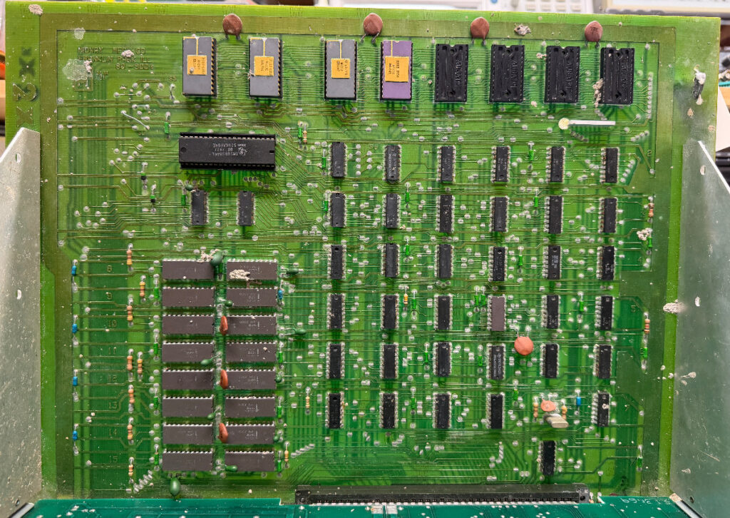
I managed to get hold of a Space Invaders arcade game board set. (80-900K)
A little bit rough though… Many chip legs has rust on them, and someone once spilled a bit cement or something similar on the board.
Bad sockets for the ROMs and CPU, so i will replace them. I will also have to remove most of the chips and put in sockets together with new chips. All RAMs and the CPU socket are now desoldered. 5 RAMs lost their legs during desoldering due to rust…
Next : ROM sockets, tantalums, capacitors and rusted ICs…
I bought this Gun Fight arcade game. (Apparantly the first arcade game with a cpu, and the first with “human to human combat”.) It is based on Intels 8080 CPU.
The cabinet seems to be quite nice for its age, only a small piece missing in the top left corner, and only a few scratches.
I also got a cardboard box with another monitor in it, a Philips 19VKUP22. Does not fit this game though. 🙂
The game boards and power supply were delivered in a cardboard box, luckily together with an extra set of boards. (Which were heavily hacked.. 🙂 ) The CPU and PROMs from the original main board were delivered desoldered and loose in the box.
I removed the transformer from the game and placed it on my workbench together with the power supply board. The power supply board had also been worked on recently. Two newer capacitors, one of them placed backwards (+/-), and the other one were in serial with a zero-ohm resistor.
This will be an interesting repair. 🙂
The power supply were repaired first and is now working. 🙂
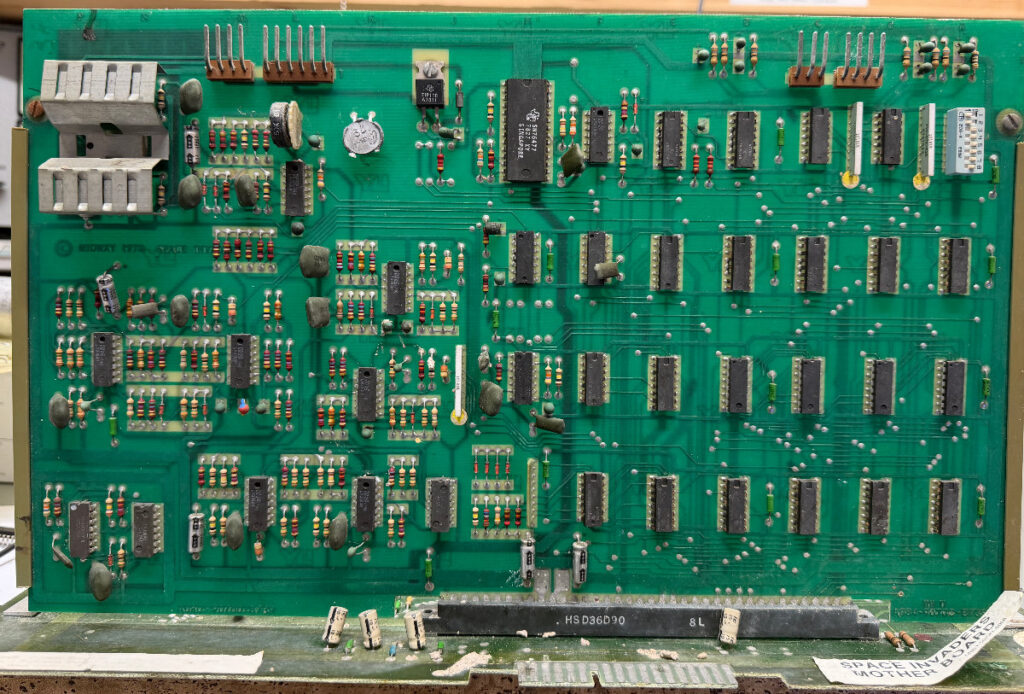
I got this Space Invaders arcade game in for repair.
I made no promises because this is my first arcade game in a cabinet, and i have never worked with arcade monitors and power supplys. Also Space Invaders CPU is an Intel 8080, which are somewhat hard to come by. Not to mention the RAMs that are almost unobtainium (For me anyway), and appearantly often goes bad on these. This will take some time.. 🙂
Measured voltages, and they were ok. I then hooked up my monitor (Philips CM-8833-II) to the game instead of the monitor that is in the cabinet, and powered it on. Garbage appeared on the screen, so the game is not booting.
The power supply i have on my workbench should deliver -5v, but when measured it only showed -4.2v, and i am not sure if that would hurt the 8080. The 8080 is appearantly sensitive to the -5v supply, if it is missing, the 8080 are likely to be destroyed. I will not risc that, så i will first have to find a solution for a power supply that delivers closer to -5v before plugging it in on my workbench and start troubleshooting.
I have now cleaned the pcb a little bit, and checked all the socketed chips. A couple of ROMs had to be changed due to corrupt data and corroded pins.
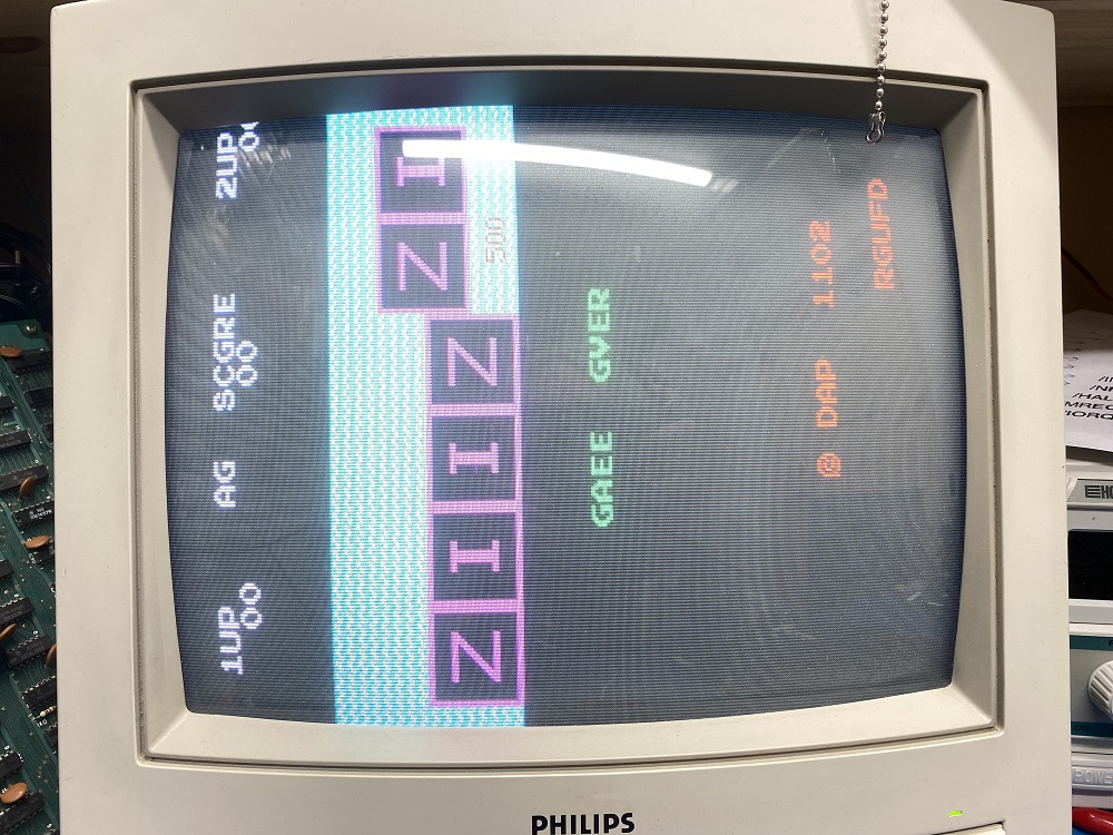
When powered up, some of the characters where wrong and the sprite were replaced with numbers.
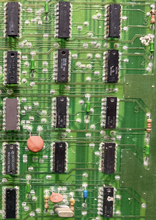
Poking around with my logic probe and oscilloscope led me to the chip at 5J (74LS245) that had a pin with “low high’s”. It looked like the high’s only reached almost 2v instead of close to 5v.
I desoldered and replaced it. Still the same.
With the board powered off, i measured the resistance of the pin to the 5v and ground pins. It was nearly shorted to ground with around 1 ohms.
With the chip out of the socket, i measured directly in the socket, with the same result. So, it seemed that it was another chip on that trace that was almost shorted. 🙂
I tracked down all the chips that was connected to that pin.
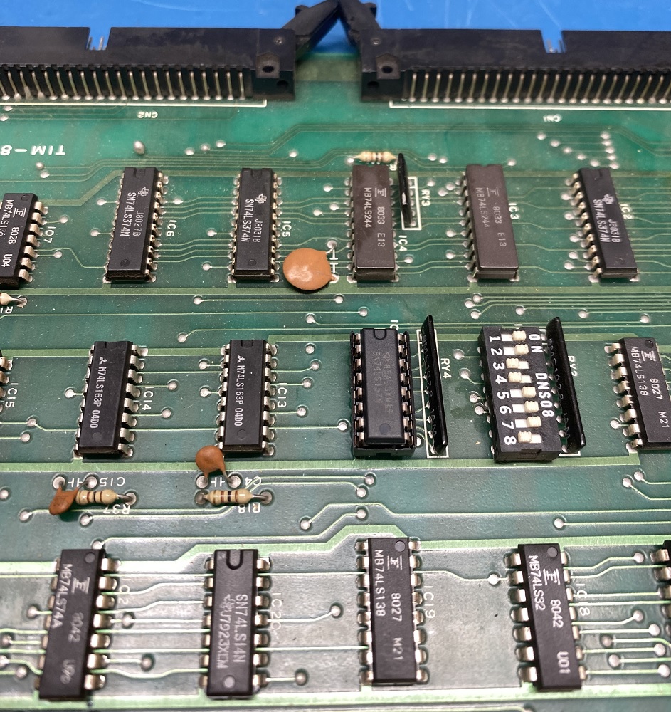
Unfortunatly i had no luck in finding the schematics for this bootleg pcb. It seems to be based on a Galaxian board, partly. One half of the board was about 85% correct with the Galaxian schematics, with some chips replaced by other types, and the other half was completely redesigned.
I found six other chips connected to that pin on 5J. I started desoldering and socketing the chips one by one, before i found the faulty one. The guilty chip was a 74LS368 at 9J. With this chip removed, the near short was gone. When measuring on the chip itself the “near short” was present.
I powered the board up without the 368 chip in 9J, and now the characters were 95% back, and the sprite seemed ok, but has orientation issues.
I have ordered a bunch of 74LS368’s and some other logic chips i was low on, so i can’t check with a working 368 just yet, but it will be interesting to see how it looks when it’s in place. 🙂
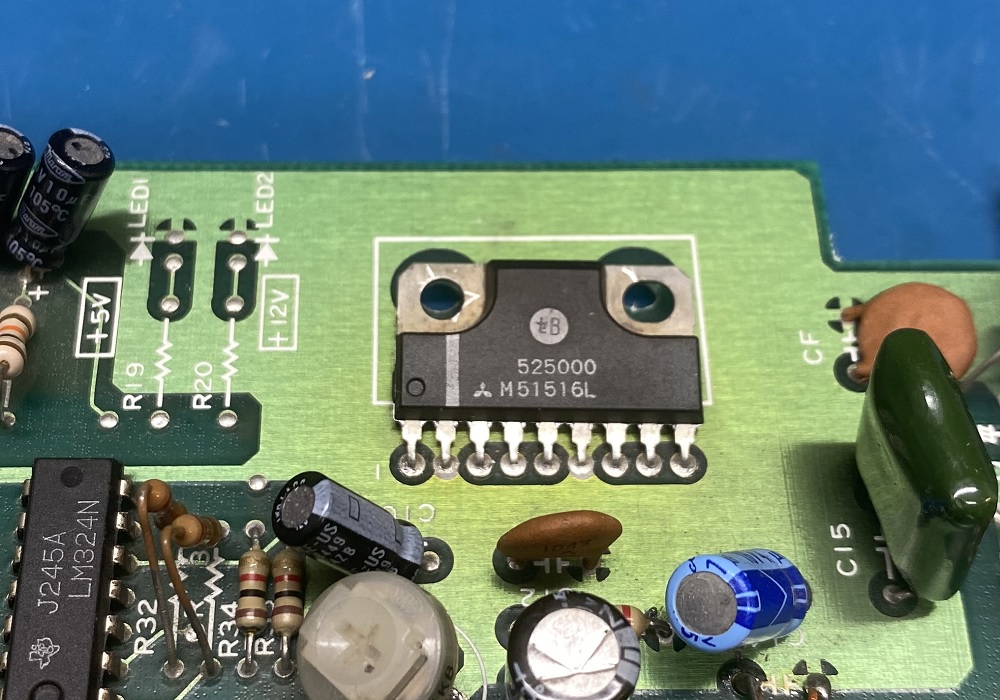
I received the new power amps yesterday, and replaced this one just now. (Yesterday morning i followed the audio signal all the way to the power amp, so it should be the power amp.)
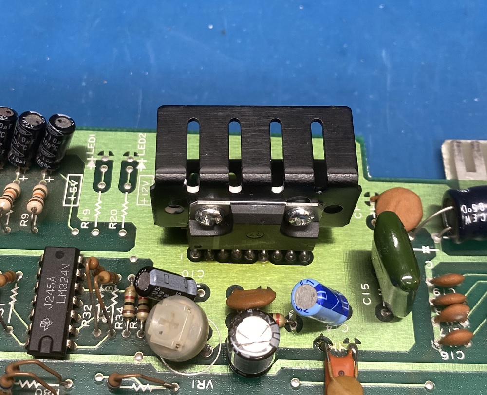
I also added a heatsink so that the new power amp may hopefully live longer.
Tested again, and the sound is back. 🙂 (There are some minor crackling noices though, so i’ll have to check/replace the caps in the audio path.)
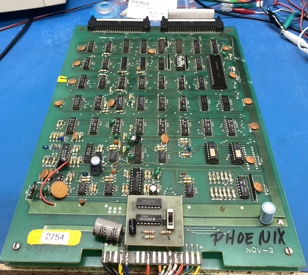
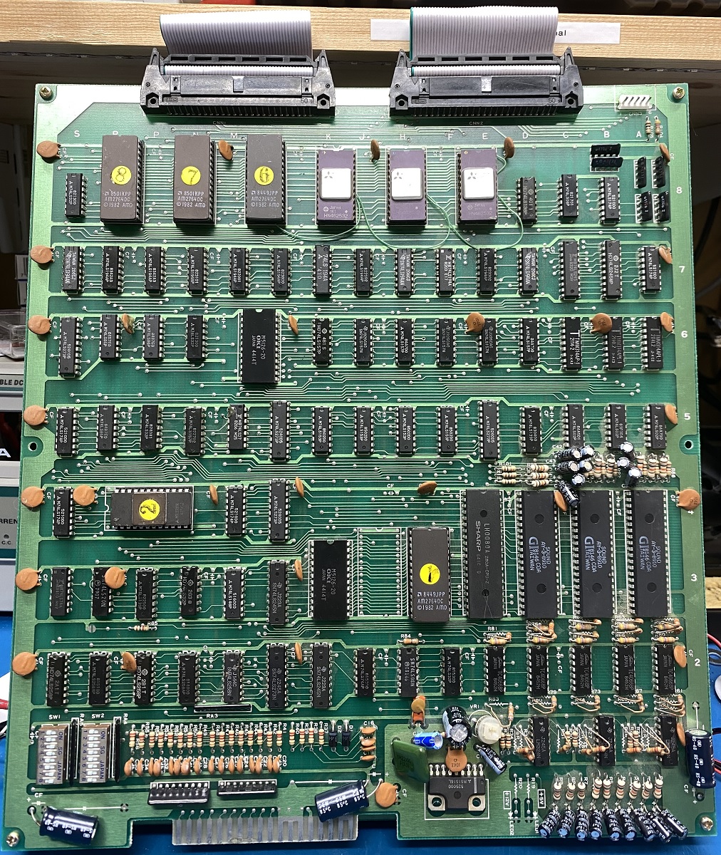
This is a “Bomb Jack” arcade game pcb. It´s a clone (“bootleg”) of the classic “Bomb Jack”.
It boots and plays, but without sound.
The sound is handled by a Z80 CPU with a 2764 EPROM containing the sounds, SRAM and three AY-3-9810 sound chips. Power amp is a M51516L.
Probing pins on the Z80 shows that clock (3 MHz) is present, /RESET and /HALT is high. /RD, /WR and /MREQ are pulsing as they should. D0-7 and A0-14 are pulsing. (A15 seems to always be low, but in the schematics it seems it’s not connected to anything special?) It looks like a small ‘X’ is scraped on the Z80 (?), so someone earlier may have suspected it to be faulty.
Probing the AY’s gives that clock (1.5 MHz)is present, CH1-3 on several of them seems to output something that seems to match when a sound should be playing.
Touching the power amp with my finger gives no static at all to the speaker. (The volume pot seems to be ok when measured.)
I have ordered 2 new power amps, and will replace it later. (Ordered one extra to have as a spare part.) While i wait for them i will try to follow the sounds towards the power amp, to see if it gets lost somewhere on the way. 🙂
This is a “Frog” arcade game pcb. It´s a clone (“bootleg”) of the classic “Frogger”.
I removed and read all the EPROM’s, and there were only one that was faulty. Gave it 15 mins in the UV eraser, and burned the correct image before i replaced it.
I have to order a couple of 36-pin connectors for this one and “ZigZag”, since i’m out of 36-pin connectors. (And Jamma connectors, so i don’t have to change the wiring when i switch between boards.)
When the connectors has arrived, i can solder it and test the board. Very interesting. 🙂
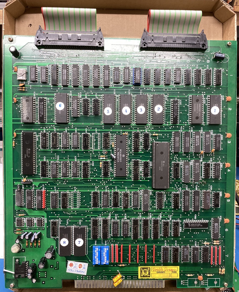
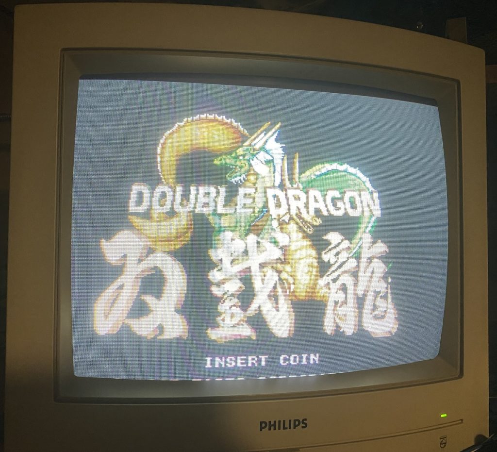
This is another “Double Dragon” arcade game pcb. This one is also a clone (“bootleg”) of the original.
During the self test, RAM and ROM was ok, but it stopped with an error (“63701 Error”).
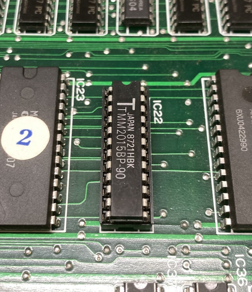
A common fault that gives this error is the SRAM TMM2015 (IC22) that is used by the 63701. I removed it, and put in a socket with a TMM2018 i got from a Choplifter spare parts board. It made no difference.
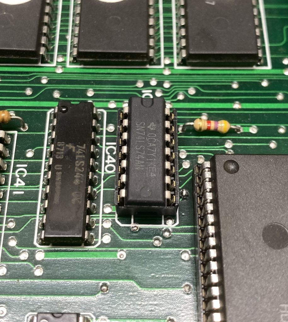
Another common fault for the “63701 Error” is the 74LS74 (IC39) next to the 63701. I removed it, and put in a socket with a new 74LS74. This solved the problem with the “63701 Error”. The game now shows its startup screen with the Dragon, and the music plays. Great, i thought. 🙂
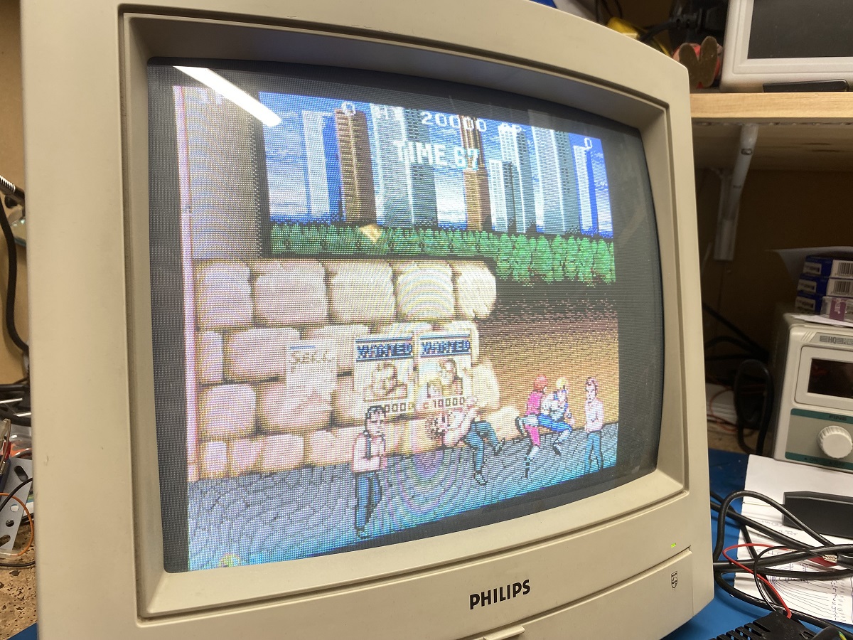
But when the game play demo started, there were background and music, but no sprites.. It also did no side scrolling, so it seemed not to be running. But after a minute or two, the sprites showed up in their initial positions. Not moving at all. After another minute or so, they moved one position, and froze again. So it seemed to be running, but halts irregularly between the moves. (Sometimes the screen went garbled after a while, but the music continued to play.)
Interesting.. 🙂
Noted that pin 2 (/NMI) on the 6809 CPU was at 3.3v all the time with no changes at all. Compared with my working Double Dragon pcb, and on that board it was at 4.4v, with sporadic “LOW:s”.
I followed that pin to a 74LS74 (IC73, although on my bootleg version it is marked IC72 on the pcb.). I piggybacked a new 74LS74, and tried the game again. It now worked normally.
So i removed it, and put in a socket with a new 74LS74.
This is a “Double Dragon” arcade game pcb. It´s a clone (“bootleg”) of the original.
This one turned out to be an easy fix.
It did not boot, instead a garbled screen was all i got. Strangely enough, when powered on for like the tenth time it booted right up and worked fine. (?) I tried to start it up again and the garbled screen was back.
Apparently something to do with the initialization of the board. When i took a good look at the board around the CPU that is used for the initialization, i noticed a capacitor that had one leg disconnected. Turned out it was the decoupling capacitor for the +5v. I changed the capacitor to a new 10 uf capacitor, and powered up the board. It booted perfectly. Tried it 3 more times, and it worked every time. This board is now repaired. 🙂
I have another Double Dragon board that will be a more powerful enemy, because it complains about the large 64-pin chip (HD63701YOP). More about that board later. 🙂