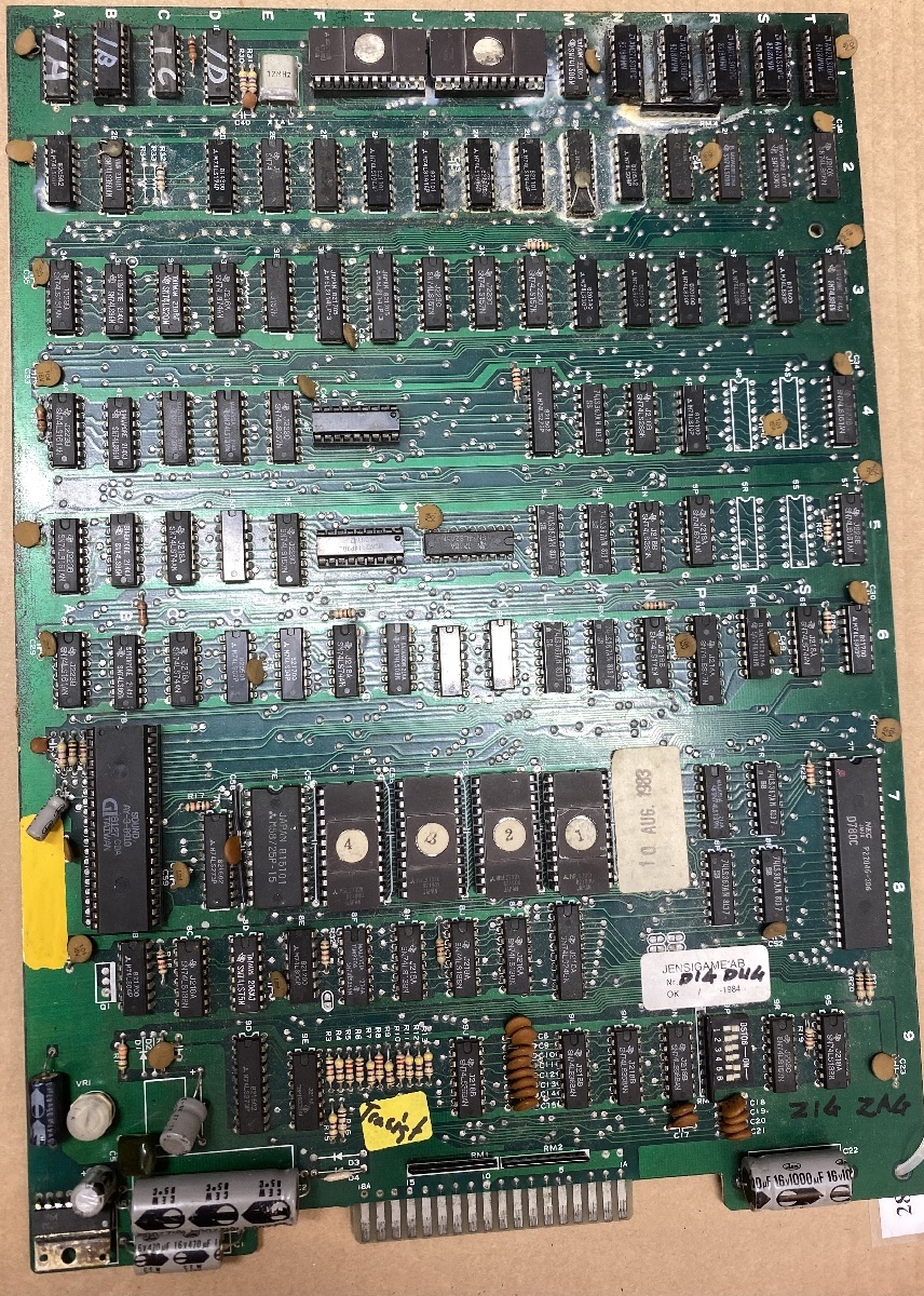
I have now cleaned the pcb a little bit, and checked all the socketed chips.
A couple of ROMs had to be changed due to corrupt data and corroded pins.
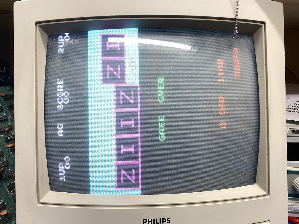
When powered up, some of the characters where wrong and the sprite were replaced with numbers.
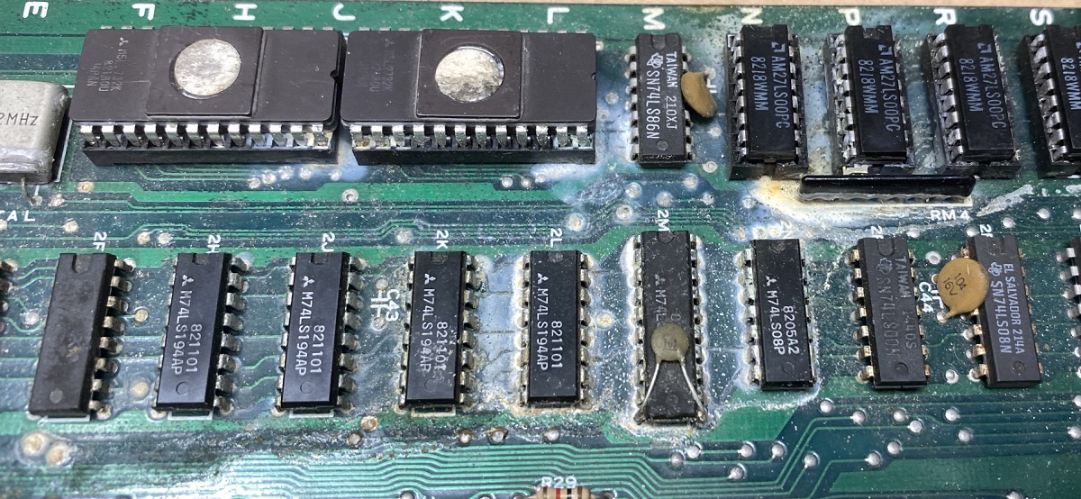
Poking around with my logic probe and oscilloscope led me to the chip at 5J (74LS245) that had a pin with “low high’s”.
It looked like the high’s only reached almost 2v instead of close to 5v.
I desoldered and replaced it.
Still the same.
With the board powered off, i measured the resistance of the pin to the 5v and ground pins.
It was nearly shorted to ground with around 1 ohms.
With the chip out of the socket, i measured directly in the socket, with the same result.
So, it seemed that it was another chip on that trace that was almost shorted. 🙂
I tracked down all the chips that was connected to that pin.
Unfortunatly i had no luck in finding the schematics for this bootleg pcb.
It seems to be based on a Galaxian board, partly.
One half of the board was about 85% correct with the Galaxian schematics, with some chips replaced by other types, and the other half was completely redesigned.
I found six other chips connected to that pin on 5J.
I started desoldering and socketing the chips one by one, before i found the faulty one.
The guilty chip was a 74LS368 at 9J.
With this chip removed, the near short was gone.
When measuring on the chip itself the “near short” was present.
I powered the board up without the 368 chip in 9J, and now the characters were 95% back, and the sprite seemed ok, but has orientation issues.
I have ordered a bunch of 74LS368’s and some other logic chips i was low on, so i can’t check with a working 368 just yet, but it will be interesting to see how it looks when it’s in place. 🙂
To be continued. 🙂