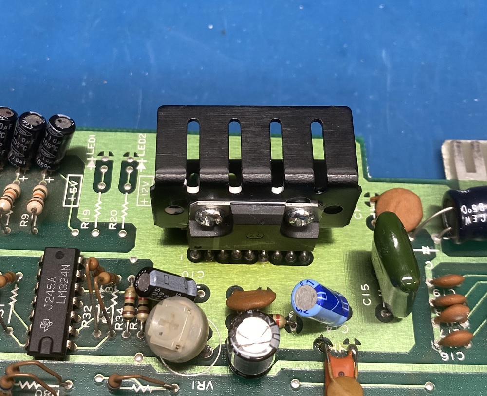
I received the new power amps yesterday, and replaced this one just now. (Yesterday morning i followed the audio signal all the way to the power amp, so it should be the power amp.)
I also added a heatsink so that the new power amp may hopefully live longer.
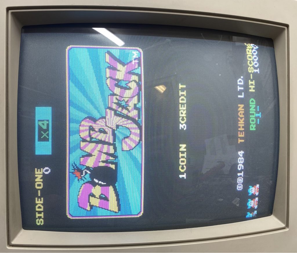
Tested again, and the sound is back. 🙂 (There are some minor crackling noices though, so i’ll have to check/replace the caps in the audio path.)
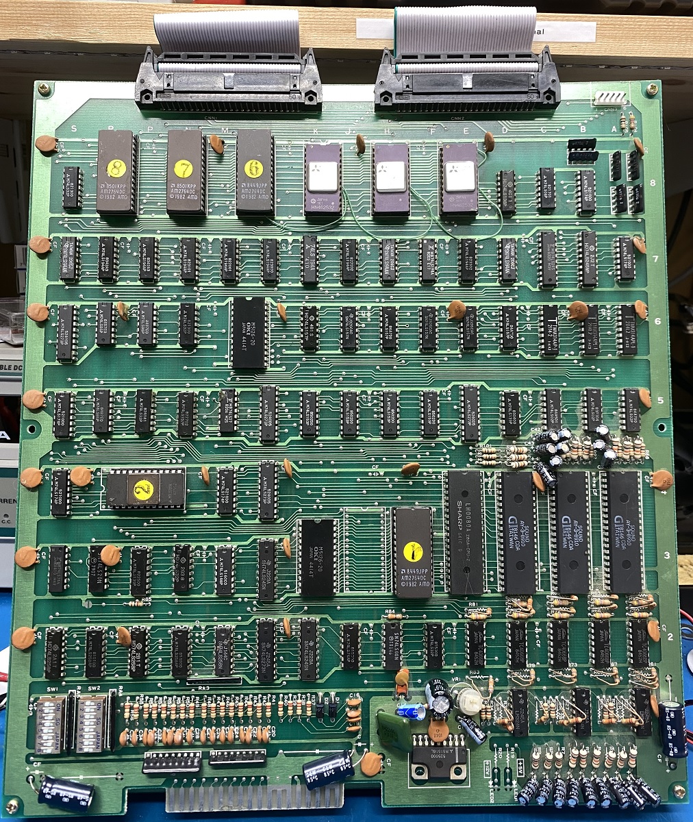
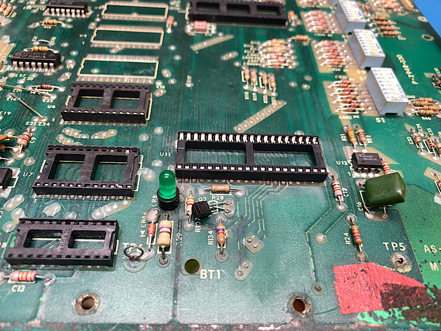
This is a “Bomb Jack” arcade game pcb. It´s a clone (“bootleg”) of the classic “Bomb Jack”.
It boots and plays, but without sound.
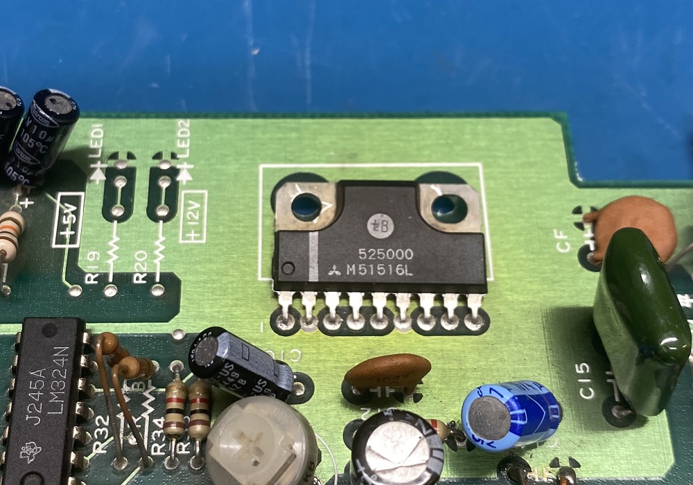
The sound is handled by a Z80 CPU with a 2764 EPROM containing the sounds, SRAM and three AY-3-9810 sound chips. Power amp is a M51516L.
Probing pins on the Z80 shows that clock (3 MHz) is present, /RESET and /HALT is high. /RD, /WR and /MREQ are pulsing as they should. D0-7 and A0-14 are pulsing. (A15 seems to always be low, but in the schematics it seems it’s not connected to anything special?) It looks like a small ‘X’ is scraped on the Z80 (?), so someone earlier may have suspected it to be faulty.
Probing the AY’s gives that clock (1.5 MHz)is present, CH1-3 on several of them seems to output something that seems to match when a sound should be playing.
Touching the power amp with my finger gives no static at all to the speaker. (The volume pot seems to be ok when measured.)
I have ordered 2 new power amps, and will replace it later. (Ordered one extra to have as a spare part.) While i wait for them i will try to follow the sounds towards the power amp, to see if it gets lost somewhere on the way. 🙂
This is a “Frog” arcade game pcb. It´s a clone (“bootleg”) of the classic “Frogger”.
I removed and read all the EPROM’s, and there were only one that was faulty. Gave it 15 mins in the UV eraser, and burned the correct image before i replaced it.
I have to order a couple of 36-pin connectors for this one and “ZigZag”, since i’m out of 36-pin connectors. (And Jamma connectors, so i don’t have to change the wiring when i switch between boards.)
When the connectors has arrived, i can solder it and test the board. Very interesting. 🙂
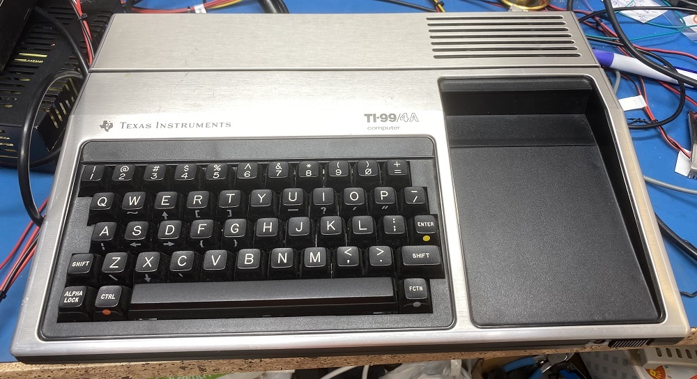
This is a Texas TI-99/4A home computer released in 1981. I have had this one for like twenty years or so, but never used it. (Got it from a friend that never used it either. 🙂 )
It is working, but just had RF output via an external RF box. (It uses a 6-pin DIN that puts out component video, Red, Green and Blue.)
But since i want to use composite video, i had to do a mod. 🙂
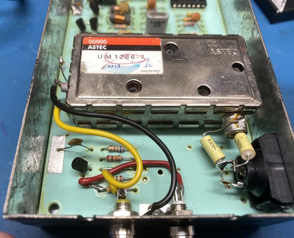
There is a mod for the external PAL RF modulator, model PHA 2036. It makes it possible to add one composite RCA connector and an audio RCA connector.
It was an easy mod, i just drilled two holes for the RCA’s and soldered three wires. 🙂 The description of the mod said nothing about insulating the RCA’s from ground though. After beeping out ground vs video ground, i noticed that they were not connected. If i just mounted the RCA’s as they were, the ground and video ground would be connected. So, i isolated the RCA’s from ground with some electrical tape, just to be sure.
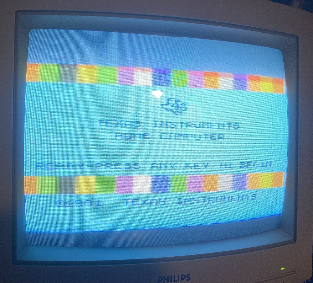
After this, the composite video worked, but i still have to see if the audio works. I have never used a TI-99/4A before, so i have to figure out how to get it to produce sound. 🙂
Next step will be to try to get it connected to my PC to see if i can get it to load a program. 🙂
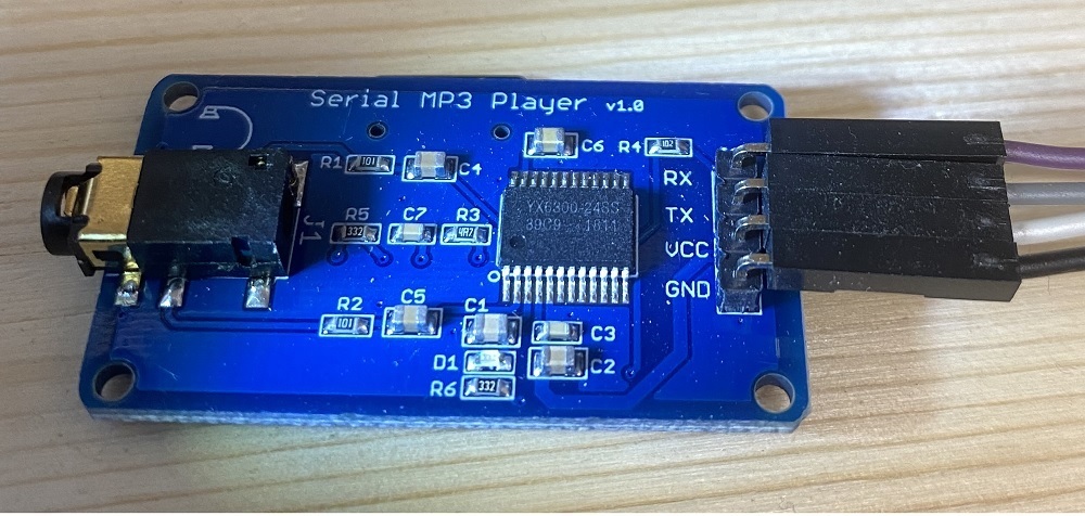
This is a MP3 module i was thinking of testing together with an Arduino.
Got this cheap from eBay a year ago, just for fun. Didn’t get it to work right away, so it were shelved for the moment.
Played around with it now, and discovered that the chip on my module were newer than the chip used in the example code i tried with. (My chip : YX6300, and the one i found code for : YX5300.) It seems that they were not quite compatible with each other. 🙂
Found an example for the same type of chip i have (YX6300), and now it works. 🙂
Now, the only question is where to use it… 🙂 The future will tell.
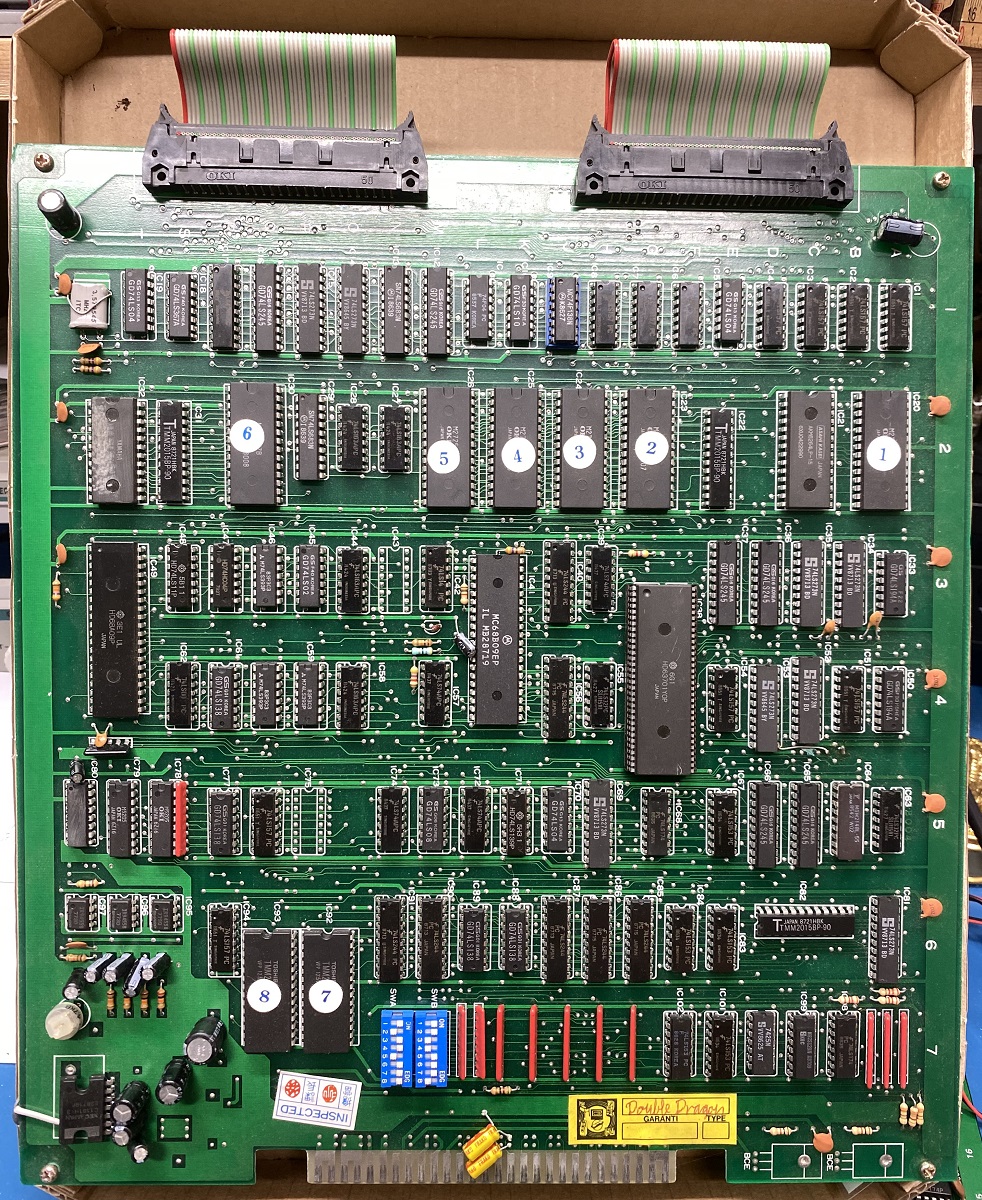
This is another “Double Dragon” arcade game pcb. This one is also a clone (“bootleg”) of the original.
During the self test, RAM and ROM was ok, but it stopped with an error (“63701 Error”).
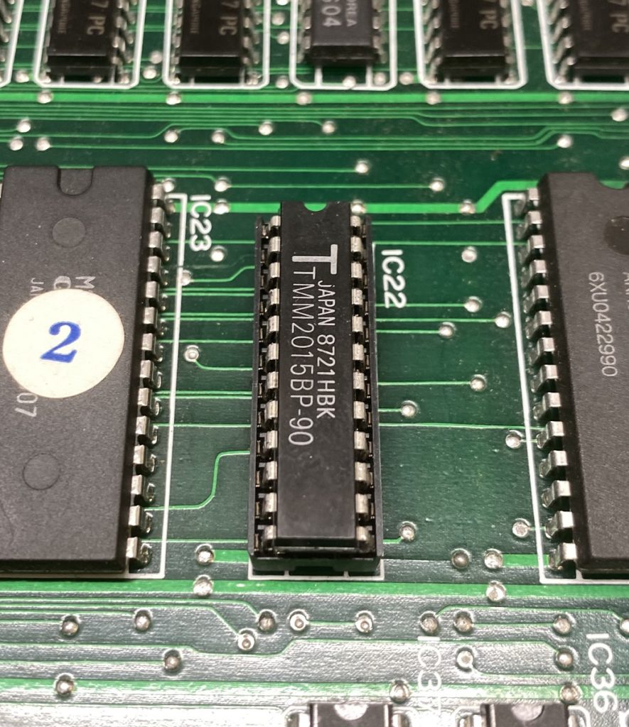
A common fault that gives this error is the SRAM TMM2015 (IC22) that is used by the 63701. I removed it, and put in a socket with a TMM2018 i got from a Choplifter spare parts board. It made no difference.
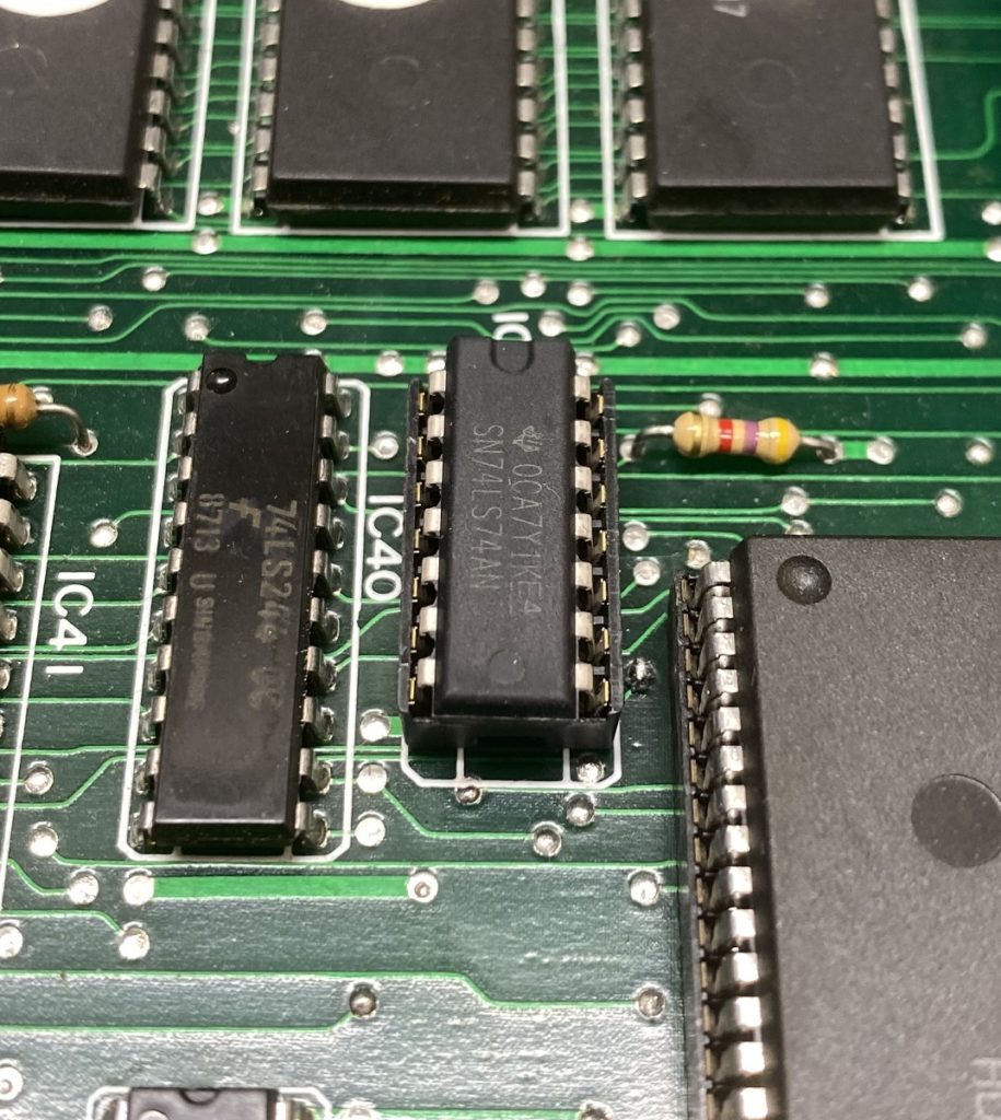
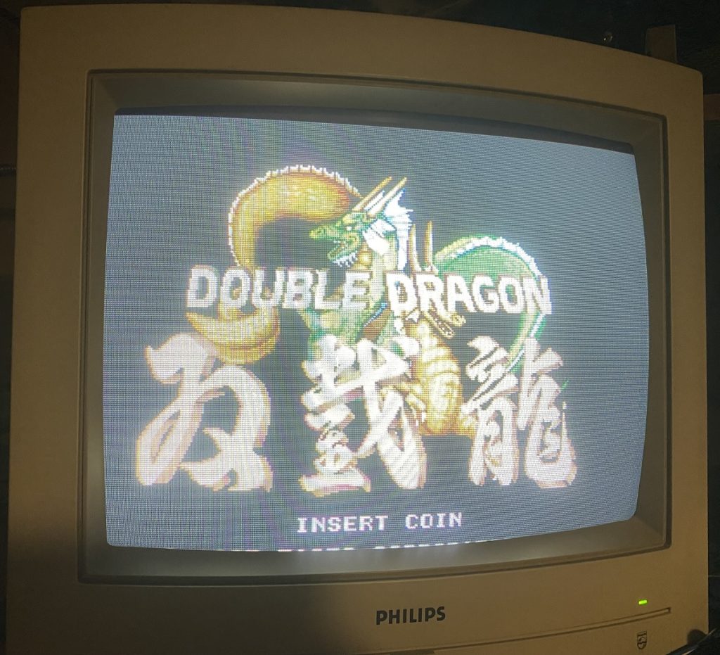
Another common fault for the “63701 Error” is the 74LS74 (IC39) next to the 63701. I removed it, and put in a socket with a new 74LS74. This solved the problem with the “63701 Error”. The game now shows its startup screen with the Dragon, and the music plays. Great, i thought. 🙂
But when the game play demo started, there were background and music, but no sprites.. It also did no side scrolling, so it seemed not to be running. But after a minute or two, the sprites showed up in their initial positions. Not moving at all. After another minute or so, they moved one position, and froze again. So it seemed to be running, but halts irregularly between the moves. (Sometimes the screen went garbled after a while, but the music continued to play.)
Interesting.. 🙂
Noted that pin 2 (/NMI) on the 6809 CPU was at 3.3v all the time with no changes at all. Compared with my working Double Dragon pcb, and on that board it was at 4.4v, with sporadic “LOW:s”.
I followed that pin to a 74LS74 (IC73, although on my bootleg version it is marked IC72 on the pcb.). I piggybacked a new 74LS74, and tried the game again. It now worked normally.
So i removed it, and put in a socket with a new 74LS74.
This is a “Double Dragon” arcade game pcb. It´s a clone (“bootleg”) of the original.
This one turned out to be an easy fix.
It did not boot, instead a garbled screen was all i got. Strangely enough, when powered on for like the tenth time it booted right up and worked fine. (?) I tried to start it up again and the garbled screen was back.
Apparently something to do with the initialization of the board. When i took a good look at the board around the CPU that is used for the initialization, i noticed a capacitor that had one leg disconnected. Turned out it was the decoupling capacitor for the +5v. I changed the capacitor to a new 10 uf capacitor, and powered up the board. It booted perfectly. Tried it 3 more times, and it worked every time. This board is now repaired. 🙂
I have another Double Dragon board that will be a more powerful enemy, because it complains about the large 64-pin chip (HD63701YOP). More about that board later. 🙂
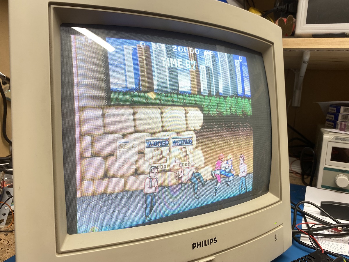
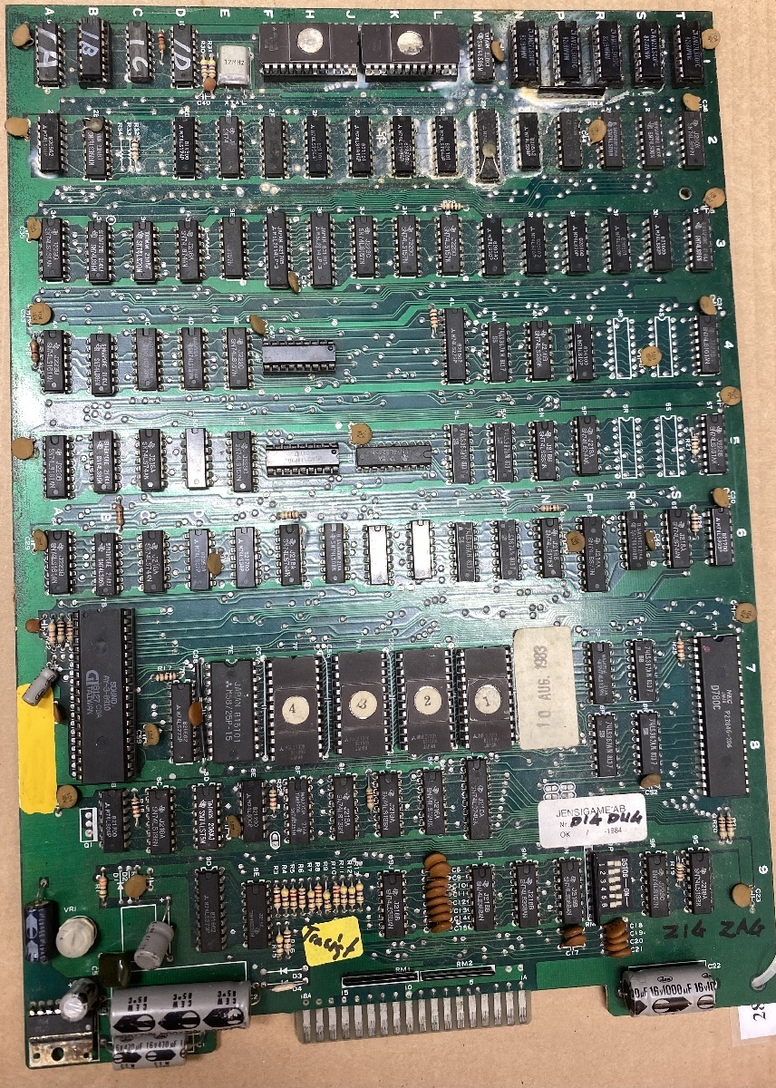
This is a “Zig Zag” arcade game pcb. It is a clone (“bootleg”) of the classic “Dig Dug”.
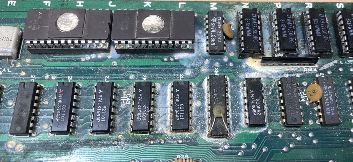
As you can see, this one is in pretty bad shape with a lot of corrosion.
The pinout of the connector is also unknown since it is fewer pins on this one compared to the original pcb. So i will have to figure out how to connect it.
I have never powered this one up, due to the obvious need of restoration. 🙂 My guess is that it is not working. 🙂
First step will be to give it a good clean, and try to reduce the amount of corrosion.