Silverball Mania update #1

It is now up and running, but with one of my other working MPU boards that were on stock.
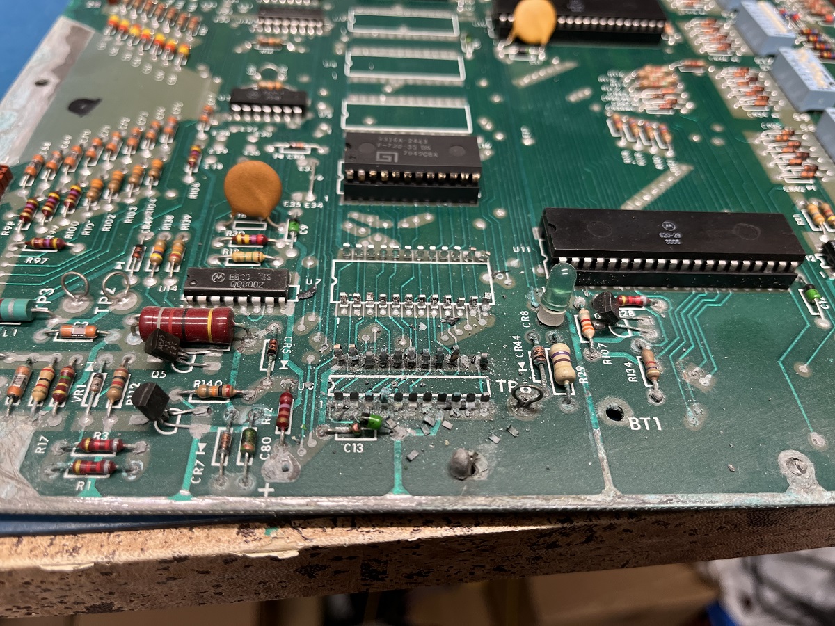
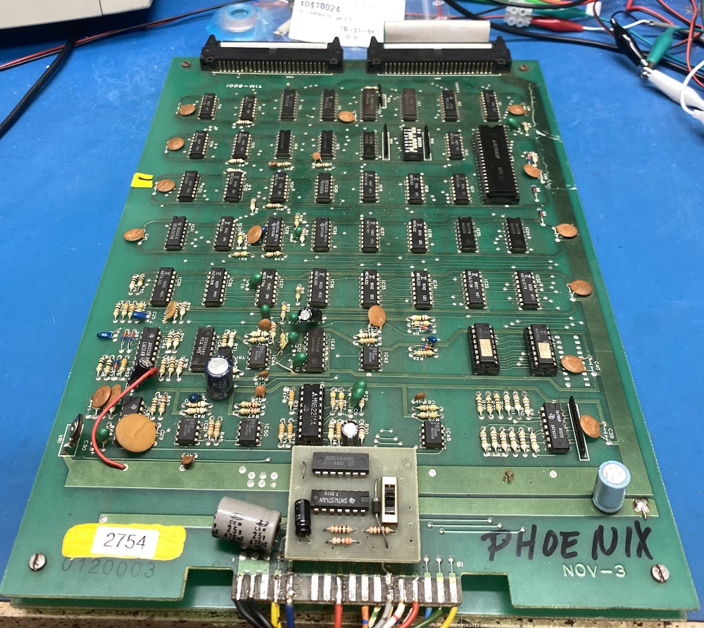
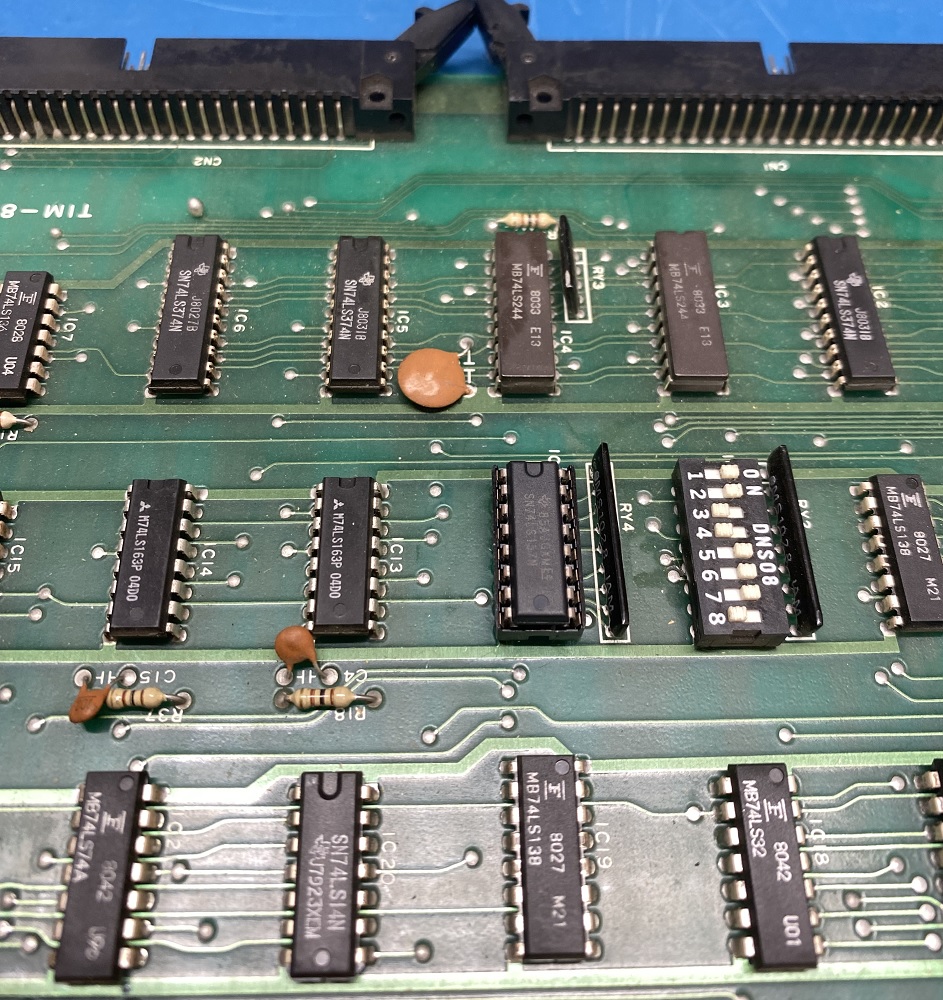
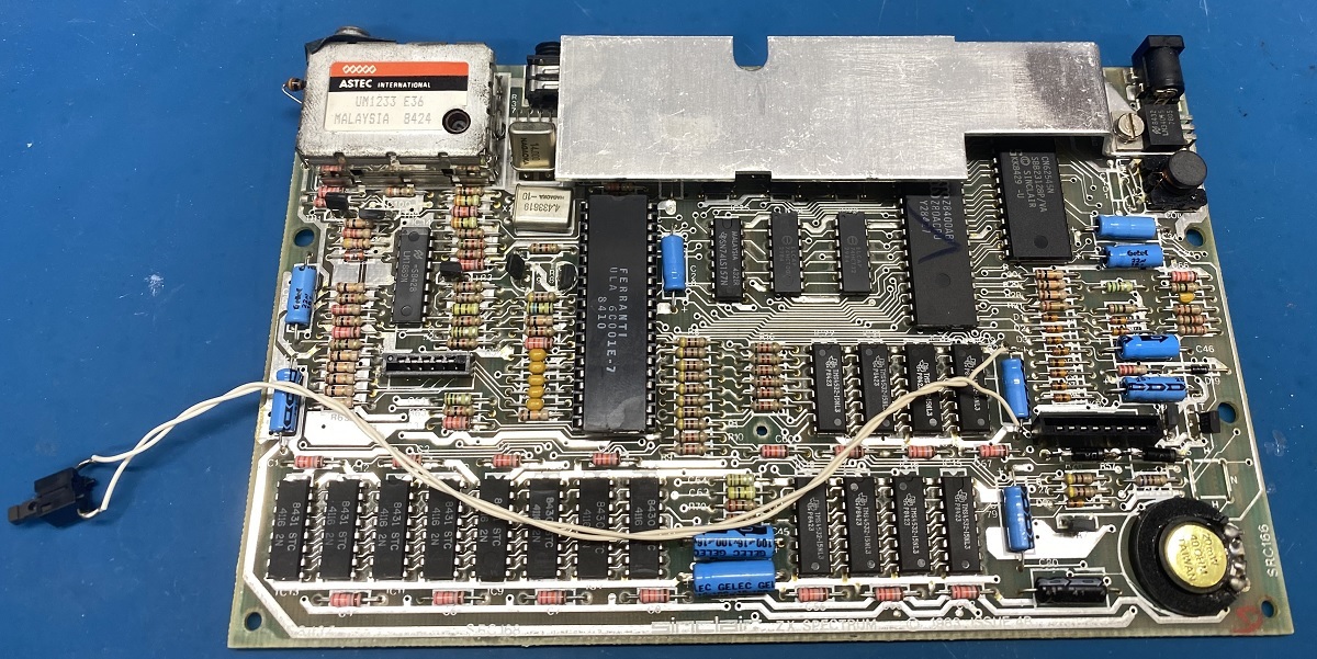
I have started to work with the MPU board that was in this game.
(Acid and component removal.)

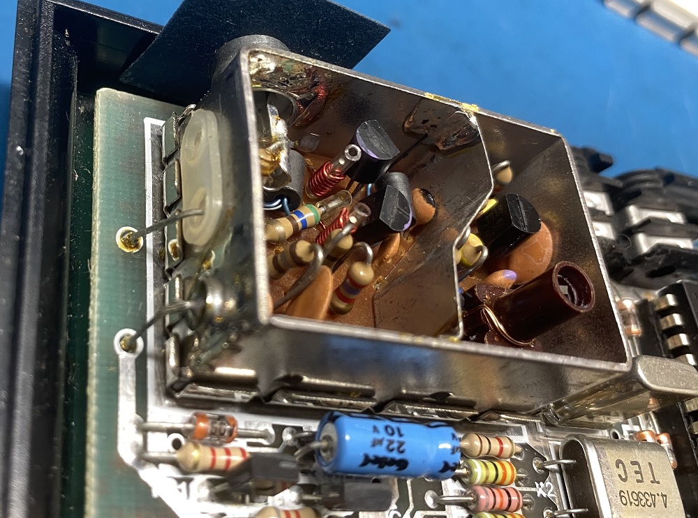
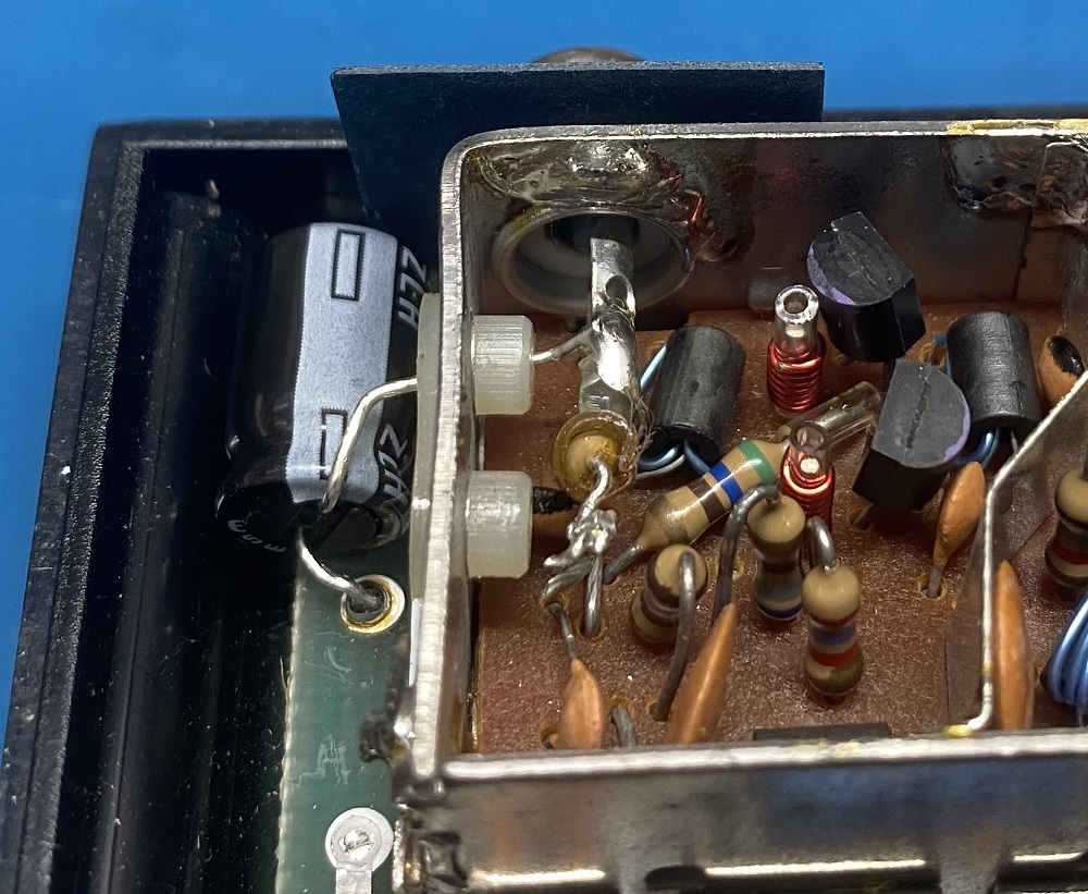
The solenoid board was repaired, the only damage was the high voltage section.
All transistors were bad and the resistor at R51 was torched, so all components in the high voltage section were replaced.
I only kept some of the resistors that were still ok.
The capacitor for the high voltage are still the same because i donΒ΄t have a new one on stock, but will get it asap.

The capacitor for the 5v were replaced, and i also did the “future proofing”.
(Adding ground jumpers for the capacitors.)

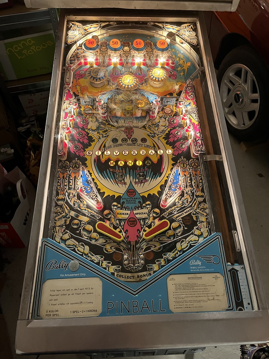
All the #44 bulbs were replaced with new ones, and all the rubbers are new.

All the plastics were cleaned and polished.
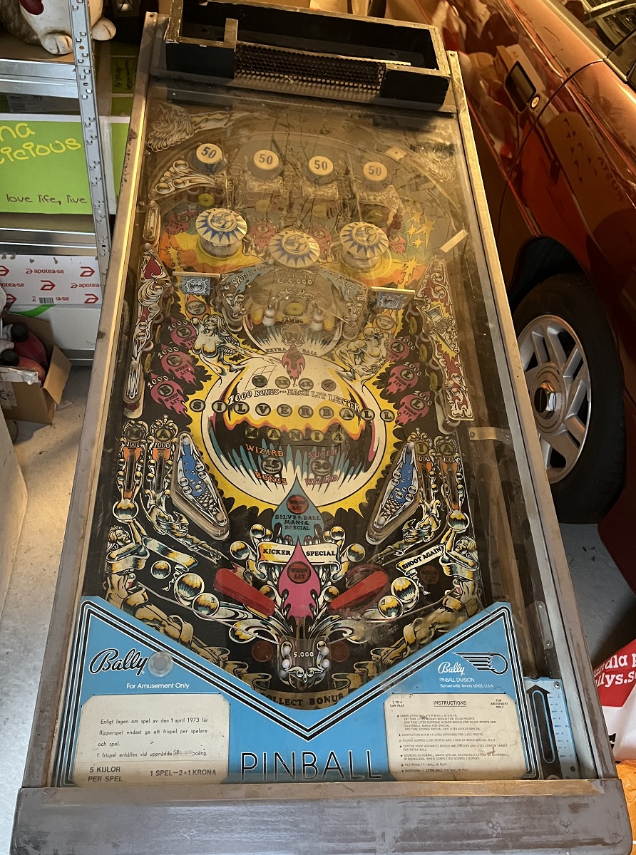
(The playfield also got a light cleaning.)

The rectifier board needed a new fuse holder for the GI.
I also cleaned the header pins, and replaced the plastic connectors terminal pins.
(The cleaning of the header pins is a temporary fix, i still need to replace all three of them when i receive the new ones that i ordered.)

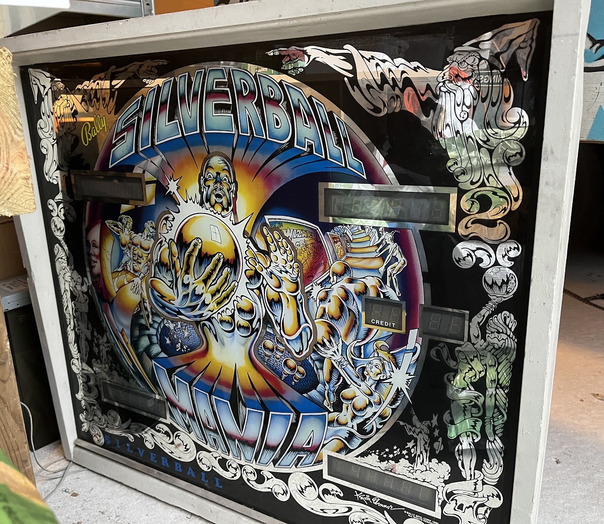
Two displays were replaced with working used ones.
(One of the two bad displays blew the fuse in the high voltage section, and the other one was simply not working.)

Things that still need some attention :

The lamp socket at the left pop bumper needs to be replaced.
It has a voltage drop between the underside and the socket on the top side, so the bulb will not come on.

The lamp socket at the last letter A in “MANIA” have a bad connection.
Needs to be cleaned or replaced.

MPU board needs some components and traces replaced due to corrosion from the battery acid.

The three .156″ headers on the rectifier board needs to be replaced with new ones.

Bally Silverball Mania pinball machine

I bought this Bally Silverball Mania pinball machine (Made 1980) two days ago.
It was listed as non working.
It stood in a corner of a garage and has probably not been working for several years.
All the rubber bands has dried out with cracks in them, and one flipper rubber had snapped off and was just laying there semi-attached.
When i prepared it for transport and was to take out the ball, it was missing. πŸ™‚

The MPU-board seem to still have itΒ΄s original battery.
(Yes, it has leaked.. πŸ™‚ )

I will not even try to power it up in this state.
Firstly i will have to check all the boards, and replace burnt connectors etc.
(Voltages, capacitor changes, solenoid board upgrading and so forth.)

All this is coming, so just wait for it. πŸ™‚

The playfield doesnΒ΄t seem to be badly worn, with just a few small areas where the wood is visible.
The top glass seems to be in good shape.

Odin pocket watch

This is one of the pocket watches i inherited from my father about 13 years ago.
He inherited it from his parents, but it is not known exactly who used it from the beginning.

It is fully wound, but not running.
The balance is not broken, so hopefully this only needs a good clean and lubrication to get running again.

Before i took it apart i released the tension of the spring, so it wouldn’t “explode”. πŸ™‚

This is my first attempt in clock repair, and i hope to get it running again. πŸ™‚
(A pocket watch is a good start, because the mechanism is quite large compared with wrist watches.)

I don’t have any fancy small jars to securely store the parts for protection during the process, but i used what i had and are being careful. πŸ™‚

Now i have to investigate what type of oils i need, and what oil goes where before i can proceed.
Patience is the keyword here. πŸ™‚

Antique wall clock

This is a wall clock from around 1875.
I inherited this one over 20 years ago from my grandmother.
It belonged to her mother once.

This is weight driven.
It has two weights that are raised when winding.
One weight is for the clock itself, and the other one is for the clock chime.
If you do not want chimes, you simply do not wind the clock chime. πŸ™‚
(As i understand it, some mechanisms are dependant of a wound clock chime, but for now i don’t know if this clock is one of those.)

It will be interesting to see if i can get it running again or not, time will tell. πŸ™‚

It needs to be cleaned and have some brass bushings replaced due to their oval shape.
(Some of the the pivot holes has become oblong instead of round, and needs replacement.)

I need to drill out those old worn bushings to replace them, and therefore need to get some apropriate small drills.

I decided to use the Moebius 8030 oil that seems to be apropriate for wall clocks.

Phoenix, arcade pcb repair

This is a Phoenix arcade game pcb.

It booted up, but colors were wrong, and player 1 fire did not work.

I unplugged the cables between the two boards, and plugged them in again.

Colors now ok, but the fire button still not works.

I traced the fire button trace to a 74LS157 that did not produce any output for the pin used.

I pulled the chip, mounted a socket with a new chip, and now the game works like it should.

Zig Zag, arcade pcb update

I have now cleaned the pcb a little bit, and checked all the socketed chips.
A couple of ROMs had to be changed due to corrupt data and corroded pins.

When powered up, some of the characters where wrong and the sprite were replaced with numbers.

Poking around with my logic probe and oscilloscope led me to the chip at 5J (74LS245) that had a pin with “low high’s”.
It looked like the high’s only reached almost 2v instead of close to 5v.

I desoldered and replaced it.
Still the same.

With the board powered off, i measured the resistance of the pin to the 5v and ground pins.
It was nearly shorted to ground with around 1 ohms.

With the chip out of the socket, i measured directly in the socket, with the same result.
So, it seemed that it was another chip on that trace that was almost shorted. πŸ™‚

I tracked down all the chips that was connected to that pin.

Unfortunatly i had no luck in finding the schematics for this bootleg pcb.
It seems to be based on a Galaxian board, partly.
One half of the board was about 85% correct with the Galaxian schematics, with some chips replaced by other types, and the other half was completely redesigned.

I found six other chips connected to that pin on 5J.
I started desoldering and socketing the chips one by one, before i found the faulty one.
The guilty chip was a 74LS368 at 9J.
With this chip removed, the near short was gone.
When measuring on the chip itself the “near short” was present.

I powered the board up without the 368 chip in 9J, and now the characters were 95% back, and the sprite seemed ok, but has orientation issues.

I have ordered a bunch of 74LS368’s and some other logic chips i was low on, so i can’t check with a working 368 just yet, but it will be interesting to see how it looks when it’s in place. πŸ™‚

To be continued. πŸ™‚

ZX Spectrum+ 48K

This is a Sinclair ZX Spectrum+ 48k home computer released in 1984.

The Spectrum+ 48k is practically identical to a standard Spectrum 48k, with two differences :

1, The new QL-style case.

2, A reset button.

It has RF output via an RCA on the backside.
But since i want to use composite video, i will have to do a mod. πŸ™‚

The keyboard membrane have been replaced with a new one.

The 7805 +5v power regulator was also changed to a TSR 1-2450 switching regulator that does not generate any heat to keep it cooler.

It works perfectly. πŸ™‚

ZX Spectrum 48k update #2

The new keyboard membrane arrived from the UK.
I replaced the membrane and it worked perfectly.

I also replaced the 7805 5v power regulator with a TSR 1-2450 switched regulator.
This one does not produce any heat, sΓ₯ the temperature inside the Spectrum should now be very much cooler.

I also hooked up the Interface One adapter that allows connecting a microdrive.

And on the rear of the Interface One i connected the Multiface One, that allows saving programs to microdrive or tape.
It also allows to pause a game and enter a poke that for example gives endless lives in a game. πŸ™‚

Tested it all, and it works as designed.
Perfect, next project… πŸ™‚

ZX Spectrum 48k update

I got the capacitors in the mail, and replaced them all.

Apparently, the positive end of the C46 capacitor was wrongly marked on the circuit board.
I documented the capacitors on this issue two motherboard, for future use. πŸ™‚

When tested, the image still had that yellowish tone, so it was time to adjust VR1 and VR2.

I used my oscilloscope attached to the composite wire to get the noice level as small as possible.

Much better, now it is white as it should be. πŸ™‚

Can’t test anything else right now, because i am waiting for the new keyboard membrane from UK to arrive.

To be continued. πŸ™‚

ZX Spectrum 48k home computer

This is a Sinclair ZX Spectrum 48k home computer released in 1982.

I bought this one new in the mid 80’s. (This is an issue two.)
When i upgraded to a C64 i sold it to one of my cousins.
I got it back a couple of years later when my cousin was not using it anymore.
Then it has been in storage ever since.

It is booting, but with a distorted image.
It only has RF output via an RCA on the backside.
But since i want to use composite video, i will have to do a mod. πŸ™‚

The keyboard membrane connectors were bad, so i could not try anything else but to power it up.
(I have ordered a new membrane from the UK, and i will replace it when it arrives.)

All the capacitors will be replaced as well.
(Same here, had to order some and will replace them later.)

I did the composite mod and tried it on my monitor.
Much better, but with a yellowish tone.
I will adjust the VR1/VR2 when the caps have been replaced to see if this will fix it.

To be continued. πŸ™‚